Chapter 10
10-24
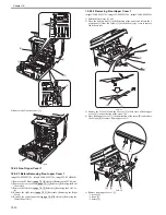
1) Remove the ETB unit.
Reference [Removing the ETB Unit]
2) Remove the fixing assembly.
Reference [Removing the Fixing
Assembly]
3) Remove the rear cover unit.
Reference [Removing the Rear
Cover Unit]
4) Remove the ADF Unit + Reader Unit.
Reference [Removing
the ADF Unit + Reader Unit]
5) Remove the left cover.
Reference [Removing the Left Cov-
er]
6) Remove the right cover.
Reference [Removing the Right
Cover]
7) Remove the Upper Frame Unit.
Reference [Removing the
Upper Frame Unit]
8) Remove the Reversal Unit.
Reference [Removing the Revers-
al Unit]
10.5.16.2 Removing the Low Voltage Power Supply PCB
0019-5739
imageCLASS MF9170c / imageCLASS MF9150c / imageCLASS MF8450c
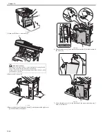
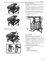
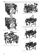
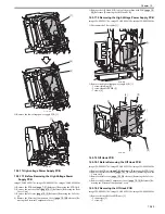
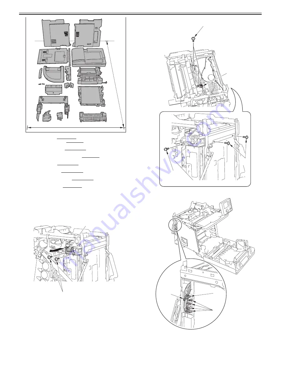
1) Remove the switch button unit [1].
- 2 screws [2]
F-10-63
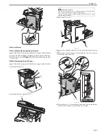
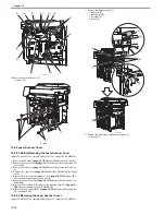
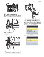
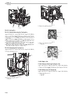
2) Disconnect the connector [1] and remove the 4 screws (TP) [2] and the
screw (with washer) [3].
F-10-64
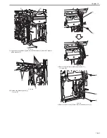
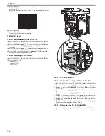
3) Remove the wire saddle [1] and disconnect the 5 connectors [2].
F-10-65
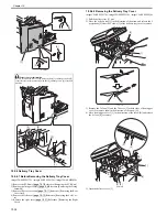
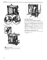
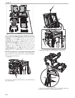
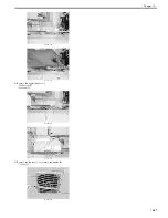
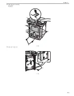
4) Move the low voltage power supply PCB [1] in the direction of the arrow,
and free the 5 harnesses [3] from the harness guide hole [2].
1100mm
1700mm
[2]
[1]
[1]
[2]
[2]
[3]
[1]
[2]
[2]
Содержание imageCLASS MF8450c
Страница 16: ...Chapter 1 Introduction ...
Страница 55: ...Chapter 2 Basic Operation ...
Страница 61: ...Chapter 3 Main Controller ...
Страница 75: ...Chapter 4 Original Exposure System ...
Страница 88: ...Chapter 5 Original Feeding System ...
Страница 105: ...Chapter 6 Laser Exposure ...
Страница 113: ...Chapter 7 Image Formation ...
Страница 150: ...Chapter 8 Pickup and Feed System ...
Страница 184: ...Chapter 9 Fixing System ...
Страница 200: ...Chapter 10 External and Controls ...
Страница 230: ...Chapter 11 Maintenance and Inspection ...
Страница 233: ...Chapter 12 Measurement and Adjustments ...
Страница 237: ...Chapter 13 Correcting Faulty Images ...
Страница 251: ...Chapter 13 13 13 13 3 5 PCBs 13 3 5 1 PCBs 0019 5065 imageCLASS MF9170c imageCLASS MF9150c imageCLASS MF8450c ...
Страница 256: ...Chapter 13 13 18 F 13 19 21 22 28 29 30 31 24 14 15 16 23 26 25 32 27 20 19 18 17 2 13 6 10 33 1 8 4 3 12 11 5 7 9 ...
Страница 260: ...Chapter 14 Error Code ...
Страница 272: ...Chapter 15 Special Management Mode ...
Страница 280: ...Chapter 16 Service Mode ...
Страница 322: ...Chapter 17 Upgrading ...
Страница 327: ...Chapter 17 17 4 3 Click Next F 17 4 4 Select a USB connected device and click Next F 17 5 ...
Страница 328: ...Chapter 17 17 5 5 Click Start F 17 6 6 Click Yes F 17 7 Download will be started F 17 8 ...
Страница 330: ...Chapter 18 Service Tools ...
Страница 334: ...Appendix ...
Страница 349: ......

