Chapter 10
10-23
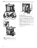
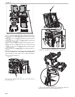
F-10-59
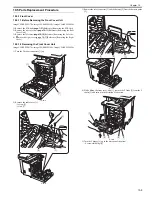
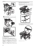
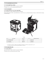
2) Remove the DC controller PCB [1].
- 4 screws [2]
F-10-60
10.5.13.3 Procedure after Replacing the DC controller
PCB
0021-0347
imageCLASS MF9170c / imageCLASS MF9150c / imageCLASS MF8450c
After replacing the DC controller PCB, restore the backup data from the
main controller PCB.
1) Using the service mode, restore the backup data of the DC controller
stored in NVRAM of the main controller PCB to NVRAM of the DC con-
troller PCB.
COPIER> FUNCTION> VIFFNC> RSTR-DCN
2) Execute "Initial Setting/Registration > Adjustment/Cleaning > Automatic
Gradation Correction > Full Correction".
10.5.14 Memory Controller PCB
10.5.14.1 Before Removing the Memory Controller PCB
0020-3352
imageCLASS MF9170c / imageCLASS MF9150c / imageCLASS MF8450c
1) Remove the ETB unit.
Reference [Removing the ETB Unit]
2) Remove the rear cover unit.
Reference [Removing the Rear
Cover Unit]
3) Remove the left cover.
Reference [Removing the Left Cov-
er]
4) Remove the right cover.
Reference [Removing the Right
Cover]
5) Remove the Electrical Components Cover.
Reference [Re-
moving the Electrical Components Cover]
6) Remove the Controller Box.
Reference [Removing the Con-
troller Box]
7) Remove the Off Hook PCB. (only of the machine with FAX)
Reference [Removing the Off Hook PCB]
8) Remove the DC Controller PCB.
Reference [Removing the
DC Controller PCB]
9) Remove the Laser Scanner Cover.
Reference [Removing the
Laser Scanner Cover]
10.5.14.2 Removing the Memory Controller PCB
0019-5777
imageCLASS MF9170c / imageCLASS MF9150c / imageCLASS MF8450c
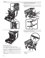
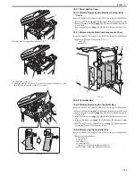
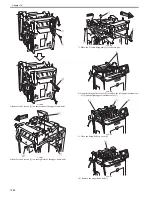
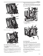
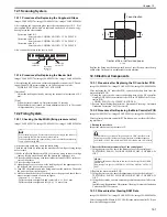
1) Remove the memory controller PCB [1].
- 4 connectors [2]
- 3 screws [3]
F-10-61
10.5.15 Duplexing Driver PCB
10.5.15.1 Before Removing the Duplex Driver PCB
0019-5742
imageCLASS MF9170c / imageCLASS MF9150c / imageCLASS MF8450c
1) Remove the ETB unit.
Reference [Removing the ETB Unit]
2) Remove the rear cover unit.
Reference [Removing the Rear
Cover Unit]
3) Remove the right cover.
Reference [Removing the Right
Cover]
10.5.15.2 Removing the Duplex Driver PCB
0019-5743
imageCLASS MF9170c / imageCLASS MF9150c / imageCLASS MF8450c
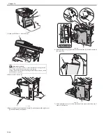
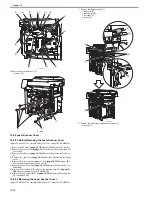
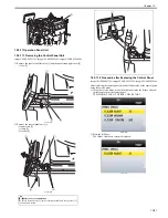
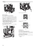
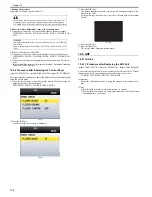
1) Remove the duplex driver PCB [1].
- 3 connectors [2]
- 3 screws [3]
F-10-62
10.5.16 Low-voltage Power Supply PCB
10.5.16.1 Before Removing the Low-Voltage Power
Supply PCB
0019-5738
imageCLASS MF9170c / imageCLASS MF9150c / imageCLASS MF8450c
[1]
[1]
[2]
[2]
[1]
[2]
[2]
[1]
[2]
[1]
[2]
[2]
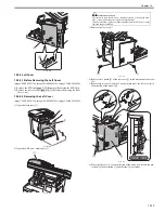
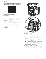
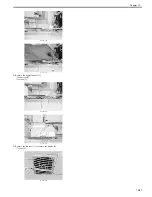
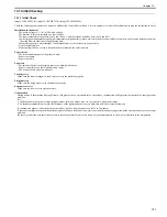
MEMO:
19 parts (e.g.: external cover, unit) need to be removed when removing the
low voltage power supply PCB. Be sure to have enough space equivalent to
1,700mm x 1,100mm for storing parts.
[1]
[3]
[2]
[1]
[2]
[2]
[3]
[3]
Содержание imageCLASS MF8450c
Страница 16: ...Chapter 1 Introduction ...
Страница 55: ...Chapter 2 Basic Operation ...
Страница 61: ...Chapter 3 Main Controller ...
Страница 75: ...Chapter 4 Original Exposure System ...
Страница 88: ...Chapter 5 Original Feeding System ...
Страница 105: ...Chapter 6 Laser Exposure ...
Страница 113: ...Chapter 7 Image Formation ...
Страница 150: ...Chapter 8 Pickup and Feed System ...
Страница 184: ...Chapter 9 Fixing System ...
Страница 200: ...Chapter 10 External and Controls ...
Страница 230: ...Chapter 11 Maintenance and Inspection ...
Страница 233: ...Chapter 12 Measurement and Adjustments ...
Страница 237: ...Chapter 13 Correcting Faulty Images ...
Страница 251: ...Chapter 13 13 13 13 3 5 PCBs 13 3 5 1 PCBs 0019 5065 imageCLASS MF9170c imageCLASS MF9150c imageCLASS MF8450c ...
Страница 256: ...Chapter 13 13 18 F 13 19 21 22 28 29 30 31 24 14 15 16 23 26 25 32 27 20 19 18 17 2 13 6 10 33 1 8 4 3 12 11 5 7 9 ...
Страница 260: ...Chapter 14 Error Code ...
Страница 272: ...Chapter 15 Special Management Mode ...
Страница 280: ...Chapter 16 Service Mode ...
Страница 322: ...Chapter 17 Upgrading ...
Страница 327: ...Chapter 17 17 4 3 Click Next F 17 4 4 Select a USB connected device and click Next F 17 5 ...
Страница 328: ...Chapter 17 17 5 5 Click Start F 17 6 6 Click Yes F 17 7 Download will be started F 17 8 ...
Страница 330: ...Chapter 18 Service Tools ...
Страница 334: ...Appendix ...
Страница 349: ......

