Chapter 9
9-1
9.1 Overview/Configuration
9.1.1 Overview
0019-5046
imageCLASS MF9170c / imageCLASS MF9150c / imageCLASS MF8450c
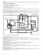
The ceramic heater fixing method is adopted on the fixing assembly of this machine.
Temperature control of the fixing assembly is performed by the fixing control circuit and the fixing heater safety circuit according to the commands from CPU
(IC1001) on DC controller PCB.
Fixing heater (H1)
A ceramic heater for heating the fixing sleeve. The heater has one piece of U-shaped heating element that practically works as 2 heaters.
Thermistors (TH1, TH2)
Thermistors for detecting the fixing temperature. The following 2 types are used.
- Fixing main thermistor (TH1): contact type thermistor for detecting the fixing sleeve temperature that is located at the center inside the fixing sleeve.
- Fixing sub thermistor (TH2): contact type thermistor for detecting the fixing heater temperature that is located at the left edge of the fixing heater.
Fixing thermal switch (TP1A)
Non-contact type thermal switch for preventing the fixing heater from overheating that is located at the center of the fixing heater. When the fixing heater overheats,
the contact point opens and power to the fixing heater is cut.
F-9-1
Fixing sleeve
Fixing main thermistor: TH1
(contact type)
Fixing sub thermistor: TH2
(contact type)
Fixing pressure roller
Fixing unit
Fixing thermal switch: TP1A
(Non-contact type)
DC controller
PCB
Fixing heater: H1
Low-voltage
power PCB
Fixing heater
drive signal
Fixing temperature signal
Fixing
heater
safety
circuit
CPU
(IC1001)
Fixing
control
circuit
Содержание imageCLASS MF8450c
Страница 16: ...Chapter 1 Introduction ...
Страница 55: ...Chapter 2 Basic Operation ...
Страница 61: ...Chapter 3 Main Controller ...
Страница 75: ...Chapter 4 Original Exposure System ...
Страница 88: ...Chapter 5 Original Feeding System ...
Страница 105: ...Chapter 6 Laser Exposure ...
Страница 113: ...Chapter 7 Image Formation ...
Страница 150: ...Chapter 8 Pickup and Feed System ...
Страница 184: ...Chapter 9 Fixing System ...
Страница 200: ...Chapter 10 External and Controls ...
Страница 230: ...Chapter 11 Maintenance and Inspection ...
Страница 233: ...Chapter 12 Measurement and Adjustments ...
Страница 237: ...Chapter 13 Correcting Faulty Images ...
Страница 251: ...Chapter 13 13 13 13 3 5 PCBs 13 3 5 1 PCBs 0019 5065 imageCLASS MF9170c imageCLASS MF9150c imageCLASS MF8450c ...
Страница 256: ...Chapter 13 13 18 F 13 19 21 22 28 29 30 31 24 14 15 16 23 26 25 32 27 20 19 18 17 2 13 6 10 33 1 8 4 3 12 11 5 7 9 ...
Страница 260: ...Chapter 14 Error Code ...
Страница 272: ...Chapter 15 Special Management Mode ...
Страница 280: ...Chapter 16 Service Mode ...
Страница 322: ...Chapter 17 Upgrading ...
Страница 327: ...Chapter 17 17 4 3 Click Next F 17 4 4 Select a USB connected device and click Next F 17 5 ...
Страница 328: ...Chapter 17 17 5 5 Click Start F 17 6 6 Click Yes F 17 7 Download will be started F 17 8 ...
Страница 330: ...Chapter 18 Service Tools ...
Страница 334: ...Appendix ...
Страница 349: ......


