4-69
d) DTMF signal output test
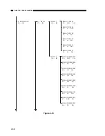
When 5 on the numeric key pad in the MODEM NCU TEST menu is pressed, the
DTMF signal transmission test is selected. This test uses the telephone line connection
terminal and the speaker to output the DTMF signals from the modem shown below.
The DTMF signal corresponds to the key pressed on the numeric key pad.
Remarks:
The output level of each signal conforms to the service mode settings.
e) Tonal, DTMF signal reception test
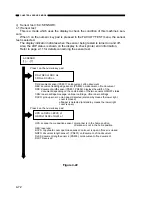
When 6 on the numeric key pad in the MODEM NCU TEST menu is pressed, the
tonal signal and DTMF signal reception 0 test is selected. This test checks whether the
tonal signal and DTMF signal received from the telephone line connection terminal was
detected.
Figure 4-21
CHAPTER 4 SERVICE MODE
4-6 : TONE Rx 000
0
0
0
Changes from 0 to 1 when a 462
±
25Hz signal is detected
Changes from 0 to 1 when a 1100
±
30Hz signal is detected
Changes from 0 to 1 when a 2100
±
25Hz signal is detected
Tonal signal reception test
4-6 : TONE Rx 000
1 2 3 4 5 6 7 8 9 0
Tonal signal reception test
The DTMF signals received on the display’s second line are displayed in order from the right.
Содержание GP160DF
Страница 6: ...COPYRIGHT 1999 CANON INC CANON GP160 REV 0 FEB 1999 PRINTED IN JAPAN IMPRIME AU JAPON iv...
Страница 12: ......
Страница 52: ......
Страница 64: ......
Страница 74: ......
Страница 86: ......
Страница 88: ......
Страница 98: ......
Страница 108: ......
Страница 110: ......
Страница 146: ......
Страница 148: ......
Страница 158: ......
Страница 186: ......
Страница 188: ......
Страница 204: ......
Страница 206: ......
Страница 224: ......
Страница 232: ......
Страница 234: ......
Страница 430: ......
Страница 432: ......
Страница 434: ...A 2 COPYRIGHT 1999 CANON INC CANON GP160 REV 0 FEB 1999 PRINTED IN JAPAN IMPRIME AU JAPON...
Страница 436: ......
Страница 446: ...PRINTED IN JAPAN IMPRIME AU JAPON 0299AB1 51 1 This publication is printed on 70 reprocessed paper...
Страница 482: ......
Страница 486: ...CHAPTER 3 ARRANGEMENT AND FUNCTIONS OF THE ELECTRICAL PARTS 3 4 B Motor fan Figure 3 2 M701 FM301 M801 M601 M651...
Страница 492: ...CHAPTER 3 ARRANGEMENT AND FUNCTIONS OF THE ELECTRICAL PARTS 3 10 E PCBs Figure 3 5 14 12 13 2 15 5 4 6 3 8 1 9 10 11 7...
Страница 622: ......
Страница 623: ......
Страница 625: ......
Страница 627: ......
Страница 635: ......
Страница 656: ...COPYRIGHT C 1999 CANON INC CANON 2220 2210 2200 160 3000 REV 1 FEB 1999 PRINTED IN JAPAN IMPRIME AU JAPON III 1...


