


COPYRIGHT © 1999 CANON INC. CANON GP160 REV.0 FEB. 1999 PRINTED IN JAPAN (IMPRIME AU JAPON)
CHAPTER 8 FIXING SYSTEM
8-5
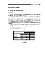
B.
Fixing heater safety mechanism
This unit is equipped with a fixing heater safety circuit, located inside the DC con-
troller PCB, which monitors the fixing temperature for abnormal rises in temperature.
Should an abnormality occur, the output from the main circuit will switch the relay (RL1),
located on the power supply PCB, to the OFF position, which cuts off the power supply
to the fixing heater.
When, due to rises in the temperature of the fixing heater, the power voltage of the
thermistor reaches 0.8V or higher (230 °C or higher), the output of the number 7 pin of
the comparator (IC304) changes to “L”. When this happens, the number 1 pin of the
IC304 changes to “L”, the Q4 changes to OFF, which causes the relay (RL1) to switch
OFF.
Furthermore, the fixing assembly has been equipped with a thermoswitch (TSW1).
Should the surface temperature of the thermoswitch reach approximately 240 °C, the
thermoswitch switches OFF, and the power supply to the fixing heater is cut off.
C.
Fixing assembly malfunction detector
Should the CPU (IC301) of the DC control PCB detect any of the conditions from ‘a’
to ‘h’, described below, it judges the fixing heater is malfunctioning and the error mes-
sage (# # 322) is displayed on the operation panel.
a. When 10 seconds have passed since the initial rotation began, and the thermistor’s
temperature is below 100°C.
b. When 50 seconds have passed since the initial rotation began, and the thermistor’s
temperature is 10°C or more below the target temperature.
c. When the fixing heater is switched on, and the temperature doesn’t rise over 15°C in
less than 0.75 seconds.
d. When the thermistor’s temperature is less than 75°C during the print temperature
control.
e. When the fixing heater’s temperature is 21 degrees or more higher than the target
temperature for 30 continuous seconds.
f.
When the fixing heater’s temperature rises to 221°C or over.
g. When there was no detection of the zero cross signal (temperature control reference
signal) after turning on the power of the main unit.
h. When there was no detection of the zero cross signal while the heater was ON for 3
or more continuous seconds.
Содержание GP160
Страница 6: ...COPYRIGHT 1999 CANON INC CANON GP160 REV 0 FEB 1999 PRINTED IN JAPAN IMPRIME AU JAPON iv ...
Страница 12: ......
Страница 52: ......
Страница 64: ......
Страница 74: ......
Страница 86: ......
Страница 88: ......
Страница 98: ......
Страница 108: ......
Страница 110: ......
Страница 146: ......
Страница 148: ......
Страница 158: ......
Страница 186: ......
Страница 188: ......
Страница 204: ......
Страница 206: ......
Страница 224: ......
Страница 232: ......
Страница 234: ......
Страница 430: ......
Страница 432: ......
Страница 434: ...A 2 COPYRIGHT 1999 CANON INC CANON GP160 REV 0 FEB 1999 PRINTED IN JAPAN IMPRIME AU JAPON ...
Страница 436: ......
Страница 446: ...PRINTED IN JAPAN IMPRIME AU JAPON 0299AB1 51 1 This publication is printed on 70 reprocessed paper ...
Страница 482: ......
Страница 486: ...CHAPTER 3 ARRANGEMENT AND FUNCTIONS OF THE ELECTRICAL PARTS 3 4 B Motor fan Figure 3 2 M701 FM301 M801 M601 M651 ...
Страница 492: ...CHAPTER 3 ARRANGEMENT AND FUNCTIONS OF THE ELECTRICAL PARTS 3 10 E PCBs Figure 3 5 14 12 13 2 15 5 4 6 3 8 1 9 10 11 7 ...
Страница 622: ......
Страница 623: ......
Страница 625: ......
Страница 627: ......
Страница 635: ......
Страница 656: ...COPYRIGHT C 1999 CANON INC CANON 2220 2210 2200 160 3000 REV 1 FEB 1999 PRINTED IN JAPAN IMPRIME AU JAPON III 1 ...


