background image

Содержание FAU-S11

Страница 1: ...COPYRIGHT 2000 CANON INC CANON FAU S11 REV 0 APR 2000 PRINTED IN JAPAN IMPRIME AU JAPON APR 2000 REVISION 0 SERVICE MANUAL ...

Страница 2: ...INC CANON FAU S11 REV 0 APR 2000 PRINTED IN JAPAN IMPRIME AU JAPON COPYRIGHT 2000 CANON INC Printed in Japan Imprimè au Japon Use of this manual should be strictly supervised to avoid disclosure of confidential information ...

Страница 3: ...COPYRIGHT 2000 CANON INC CANON FAU S11 REV 0 APR 2000 PRINTED IN JAPAN IMPRIME AU JAPON FAU S11 F96 1911 AZH000000 F96 1931 BZH000000 LIST OF SERIAL NUMBER ...

Страница 4: ...ENT 3 1 A Removing Top Cover 3 1 B Removing Hinge 3 2 C Removing FAU Cable 3 7 CHAPTER 4 MAINTENANCE AND SERVICING I PERIODICAL REPLACEMENT PARTS 4 1 II CONSUMABLE PARTS DURABILITY 4 1 III PERIODICAL SERVICING 4 1 IV SPECIAL TOOLS 4 1 V SOLVENTS AND LUBRICANTS 4 1 A Front View 1 3 B Bottom View 1 3 B Electrical System 2 2 C Inverter PCB 2 3 D Removing Inverter Cover 3 10 E Attaching the Inverter C...

Страница 5: ...COPYRIGHT 2000 CANON INC CANON FAU S11 REV 0 APR 2000 PRINTED IN JAPAN IMPRIME AU JAPON APPENDIX I GENERAL CIRCUIT DIAGRAM A 1 II INVERTER PCB CIRCUIT DIAGRAM A 2 ...

Страница 6: ...T 2000 CANON INC CANON FAU S 11 REV 0 APR 2000 PRINTED IN JAPAN IMPRIME AU JAPON CHAPTER 1 GENERAL DESCRIPTIONS I FEATURES 1 1 II SPECIFICATIONS 1 2 III EXTERIOR FEATURES 1 3 A Front View 1 3 B Bottom View 1 3 ...

Страница 7: ......

Страница 8: ...PRIME AU JAPON I FEATURES FAU S11 is a film adapter unit FAU used for CanoScan FB1210U to scan films incorporating the following features Color and monochrome negative and positive films can be scanned Film guide enables to scan 35mm film brownie film max 120 x 60mm and 4 x 5 inches film ...

Страница 9: ...ownie Max 120 x 60mm 4 x 5 inches Light Source Cold cathode fluorescent lamp Brightness 3200cd square meters 10 Operating Environment Temperature 10 to 35 degrees Relataive humidity 20 to 80 RH Power Source Supplied from CanoScan FB1210U Standard point of scanning area X 45mm Y 35mm Dimensions 285 width x 407 5 depth x 33 height mm Weight 920g Durability 20 000 times of the FAU s open close Specif...

Страница 10: ...000 CANON INC CANON FAU S11 REV 0 APR 2000 PRINTED IN JAPAN IMPRIME AU JAPON Figure 1 2 2 1 3 2 1 q Sponge Sheet w Hinge e Lamp Cover Assembly q FAU Cable w Top Cover III EXTERIOR FEATURES A Front View Figure 1 1 B Bottom View ...

Страница 11: ......

Страница 12: ...IGHT 2000 CANON INC CANON FAU S 11 REV 0 APR 2000 PRINTED IN JAPAN IMPRIME AU JAPON CHAPTER 2 OPERATION AND TIMING I BASIC OPERATION 2 1 A System Configuration 2 1 B Electrical System 2 2 C Inverter PCB 2 3 ...

Страница 13: ......

Страница 14: ...1210U to provide the light source for scanning films When the appropriate light source projects through a film and the host computer program controls the scanning unit moving charge coupled device CCD collects all the light signals of the film and synchronically generates the real analog signals The main PCB then converts the analog signal into digital signal Finally scanner driver transforms the ...

Страница 15: ...PRIME AU JAPON Inverter PCB Scanner Main PCB FAU Lamp FAU Lamp JP2 CN1 CN2 CN3 B Electrical System Electrical control of the FAU is perfromed by the main PCB in the scanner Inverter PCB performs various processing in the FAU according to the control signal sent from the main PCB Figure 2 2 ...

Страница 16: ...N1 1 2 3 JP2 1 2 3 FLON 12V GND C Inverter PCB FAU lamp ON depends on the device selection by the host computer When the scanner is powered ON the scanning lamp is turned ON When FAU is selected by the host computer as a TWAIN or Plug in Module compliant input device and application software is started the FAU lamp is turned ON and the scanning lamp is turned OFF Figure 2 3 ...

Страница 17: ...arent Plate An inverter transforms the voltage 12V supplied from the scanner into tremendously high voltages to light on two cold cathode fluorescent lamps to generate the initial light source The initial light source is transformed to an equal intensity light source through Reflective Film Light Guide Plate 1st Diffusive Film Brightness Enhancement Film BEF 2nd Diffusive Film to Transparent Plate...

Страница 18: ... APR 2000 PRINTED IN JAPAN IMPRIME AU JAPON Figure 2 5 Inverter Film 2nd Diffusive Film 1st Diffusive Film Light Enhance ment Film Transparent Plate Light Guide Plate Reflective Film Cold Cathode Fluorescent Lamp Voltage supplied from the scanner High Voltage ...

Страница 19: ......

Страница 20: ...1 REV 0 APR 2000 PRINTED IN JAPAN IMPRIME AU JAPON CHAPTER 3 MECHANICAL SYSTEM I PARTS REPLACEMENT 3 1 A Removing Top Cover 3 1 B Removing Hinge 3 2 C Removing FAU Cable 3 7 D Removing Inverter Cover 3 10 E Attaching the Inverter Cover 3 11 ...

Страница 21: ......

Страница 22: ... FAU S11 REV 0 APR 2000 PRINTED IN JAPAN IMPRIME AU JAPON 3 2 1 q Screw w Lamp Cover Assembly e Top Cover I PARTS REPLACEMENT A Removing Top Cover 1 Remove four screws from the lamp cover assembly then slide the top cover to remove it Figure 3 1 ...

Страница 23: ...3 3 2 COPYRIGHT 2000 CANON INC CANON FAU S11 REV 0 APR 2000 PRINTED IN JAPAN IMPRIME AU JAPON 1 q Hinge Cover B Removing Hinge 1 Remove the top cover 2 Push both hooks of the hinge cover to unhook it Figure 3 2 ...

Страница 24: ...3 3 COPYRIGHT 2000 CANON INC CANON FAU S11 REV 0 APR 2000 PRINTED IN JAPAN IMPRIME AU JAPON 1 2 q Hinge w Hinge Cover 3 Stand the hinges then remove the hinge cover in the arrow direction in the figure Figure 3 3 ...

Страница 25: ...CHAPTER 3 3 4 COPYRIGHT 2000 CANON INC CANON FAU S11 REV 0 APR 2000 PRINTED IN JAPAN IMPRIME AU JAPON 1 q Hinge Spring 4 Pull up the hinge spring to unhook it Figure 3 4 ...

Страница 26: ...CHAPTER 3 3 5 COPYRIGHT 2000 CANON INC CANON FAU S11 REV 0 APR 2000 PRINTED IN JAPAN IMPRIME AU JAPON 1 q Hinge 5 Turn the hinge in the arrow direction in the figure to remove it Figure 3 5 ...

Страница 27: ...CHAPTER 3 3 6 COPYRIGHT 2000 CANON INC CANON FAU S11 REV 0 APR 2000 PRINTED IN JAPAN IMPRIME AU JAPON 1 q Hinge Spring 6 Remove the left and right hinge springs from the hinge shaft Figure 3 6 ...

Страница 28: ...000 CANON INC CANON FAU S11 REV 0 APR 2000 PRINTED IN JAPAN IMPRIME AU JAPON 1 2 q Inverter Cover w Lamp Cover Assembly C Removing FAU Cable 1 Remove the top cover 2 Open the inverter cover on the lamp cover assembly Figure 3 7 ...

Страница 29: ...TER 3 3 8 COPYRIGHT 2000 CANON INC CANON FAU S11 REV 0 APR 2000 PRINTED IN JAPAN IMPRIME AU JAPON 1 2 q FAU Cable w Inverter PCB 3 Remove the FAU cable from the connector CN1 on the inverter PCB Figure 3 8 ...

Страница 30: ...CHAPTER 3 3 9 COPYRIGHT 2000 CANON INC CANON FAU S11 REV 0 APR 2000 PRINTED IN JAPAN IMPRIME AU JAPON 1 q FAU Cable Note When assembling insert the FAU cable in the recess shown in the figure Figure 3 9 ...

Страница 31: ...PAN IMPRIME AU JAPON 1 2 3 4 q Screw w Inverter Cover e Inverter PCB r Spacer D Removing Inverter Cover 1 Remove the top cover 2 Remove two screws from the inverter PCB to hold it then remove the inverter cover Figure 3 10 Note Take care not to miss two spacers under the inverter PCB ...

Страница 32: ...Inverter PCB w Inverter Cover q FAU Cable w Inverter Cover e Lamp Cable r Hook E Attaching the Inverter Cover 1 Place the inverter PCB on the inverter cover Figure 3 11 2 Draw FAU cable and lamp cable through the inverter cover cover the inverter PCB with the inverter cover then hook two hooks in the front Figure 3 12 ...

Страница 33: ...D IN JAPAN IMPRIME AU JAPON Figure 3 13 1 2 3 4 q Screw w Spacer e Lamp Cable r Recess 3 Close both sides of the inverter cover place two spacers under the inverter PCB then fasten two screws to fix the inverter PCB Note Insert the lamp cable in the recess shown in the figure ...

Страница 34: ... 11 REV 0 APR 2000 PRINTED IN JAPAN IMPRIME AU JAPON CHAPTER 4 MAINTENANCE AND SERVICING I PERIODICAL REPLACEMENT PARTS 4 1 II CONSUMABLE PARTS DURABILITY 4 1 III PERIODICAL SERVICING 4 1 IV SPECIAL TOOLS 4 1 V SOLVENTS AND LUBRICANTS 4 1 ...

Страница 35: ......

Страница 36: ...0 CANON INC CANON FAU S11 REV 0 APR 2000 PRINTED IN JAPAN IMPRIME AU JAPON I PERIODICAL REPLACEMENT PARTS None II CONSUMABLE PARTS DURABILITY None III PERIODICAL SERVICING None IV SPECIAL TOOLS None V SOLVENTS AND LUBRICANTS None ...

Страница 37: ......

Страница 38: ...COPYRIGHT 2000 CANON INC CANON FAU S 11 REV 0 APR 2000 PRINTED IN JAPAN IMPRIME AU JAPON CHAPTER 5 TROUBLESHOOTING I POSSIBLE CAUSE AND CORRECTIVE ACTION 5 1 ...

Страница 39: ......

Страница 40: ...B failure FAU cable poor connection FAU cable failure Lamp cover assembly failure Corrective Action Replace the inverter PCB Reconnect the FAU cable Replace the FAU cable Replace the lamp cover assembly Table 5 1 I POSSIBLE CAUSE AND CORRECTIVE ACTION FAU S11 may have a failure FAU lamp does not light Table 5 1 shows its possible cause and corrective action ...

Страница 41: ......

Страница 42: ...COPYRIGHT 2000 CANON INC CANON FAU S 11 REV 0 APR 2000 PRINTED IN JAPAN IMPRIME AU JAPON CHAPTER 6 PARTS CATALOG FIGURE 100 6 2 ...

Страница 43: ......

Страница 44: ...COPYRIGHT 2000 CANON INC CANON FAU S11 REV 0 APR 2000 PRINTED IN JAPAN IMPRIME AU JAPON 6 1 FAU S11 ...

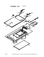
Страница 45: ...6 2 COPYRIGHT 2000 CANON INC CANON FAU S11 REV 0 APR 2000 PRINTED IN JAPAN IMPRIME AU JAPON FAU S11 FIGURE 100 7 6 5 5 3 2 1 10 9 11 8 8 12 4 3 10 4 8 ...

Страница 46: ...02 03 04 05 06 07 08 09 10 11 12 NIP N406 400 NIP N406 300 NIM L103 600 NIM L103 500 NIP N219 400 NIP N218 700 NIA YFSC 087 NIS X300 874 NIP S200 500 NIM U200 100 NIA YFSC 123 NIA YFSC 111 HINGE LEFT HINGE RIGHT SPRING 1 SPRING 2 COVER HINGE COVER TOP CABLE I F SCREW M3x8 SELF TAPP COVER INVERTER SPACER FLUORESCENT LAMP ASSEMBLY DOCUMENT COVER PP F 1 1 2 2 2 1 1 6 1 2 1 1 ...

Страница 47: ......

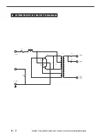
Страница 48: ...COPYRIGHT 2000 CANON INC CANON FAU S 11 REV 0 APR 2000 PRINTED IN JAPAN IMPRIME AU JAPON I GENERAL CIRCUIT DIAGRAM A 1 APPENDIX II INVERTER PCB CIRCUIT DIAGRAM A 2 ...

Страница 49: ......
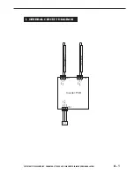
Страница 50: ... INC CANON FAU S11 REV 0 APR 2000 PRINTED IN JAPAN IMPRIME AU JAPON I GENERAL CIRCUIT DIAGRAM CHK_FAU FAU_LAMP GND 1 2 3 JP2 CN1 Inverter PCB 2 3 CHK_FAU FAU_LAMP GND 2 3 CN2 CN3 FAU Lamp 2 1 1 CHK_FAU FAU_LAMP GND FAU Lamp 1 ...

Страница 51: ...A 2 COPYRIGHT 2000 CANON INC CANON FAU S11 REV 0 APR 2000 PRINTED IN JAPAN IMPRIME AU JAPON F1 VIN GND R3 R2 R1 L1 Q1 Q2 C1 C2 CN2 3 CN3 3 CN2 1 CN3 1 C3 T1 II INVERTER PCB CIRCUIT DIAGRAM ...

Страница 52: ...COPYRIGHT 2000 CANON INC CANON FAU S11 REV 0 APR 2000 PRINTED IN JAPAN IMPRIME AU JAPON PRINTED IN JAPAN IMPRIME AU JAPON 0400M0 04 1 CANON INC ...

Отзывы: