background image

30

Using the OSD Menu


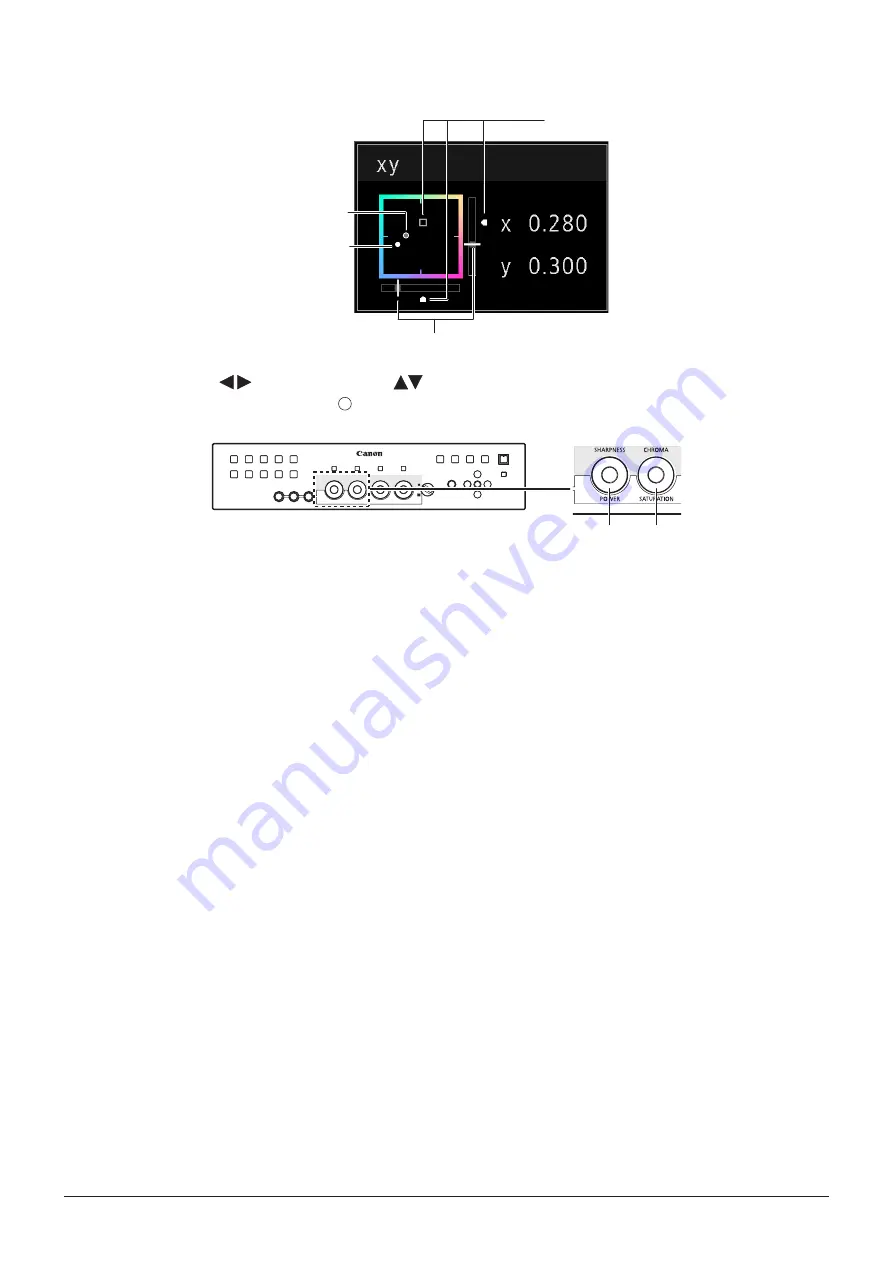
Adjusting "x, y" under "Color Temperature"

You can adjust "x, y" in "Color Temperature" on the color map.

Default value

Last used value

Current value

Current value

1.  Adjust "x" with the 


 button and "y" with 

 button.

The adjusted value is indicated by the " " mark on the color map.
You can adjust "x" using the POWER knob on the display controller and "y" using the SATURATION knob.

x

y

2.  When adjustments are completed, press the SET button.

The screen returns to the original OSD menu.

Содержание dp-v3010

Страница 1: ...play Before use be sure to read this guide including the safety and handling precautions Reading this guide will help you learn to use the video display properly Store this guide safely so that you can use it in the future English ...

Страница 2: ...nd or Wall 21 Turning on the Power 22 Turning on the Power of the Main Unit 22 Turning on Main Unit Power from the Display Controller 22 Pairing 23 Pairing the Main Unit with the Display Controller 23 Re pairing 24 Operating the Display Controller 25 Adjusting the Image Quality 25 Adjusting the Image Quality on CDL 25 Temporarily Saving Parameters Anchor Point Setting 26 Using the Function F Butto...

Страница 3: ...ings 54 Function Settings 59 System Settings 64 Signal Information 68 System Information 68 Main specifications Performance 69 Main Unit 69 Display Controller 70 Dimensions 71 Appendix 72 Supported Signal Format 72 Image Frame Display 87 Error Messages 89 Troubleshooting 91 Software Used in This Product 93 Index 95 ...

Страница 4: ... used in the manual have been simplified for clarity Conventions used in this manual Indicates a reference page Note Indicates a note Reference Indicates reference information CAUTION Indicates an item you must observe Trademarks DisplayPort and VESA are registered trademarks or trademarks of Video Electronics Standards Association in the U S and other countries Other product and company names her...

Страница 5: ...Park Melville NY 11747 U S A Tel No 631 330 5000 For the customers in Canada CAN ICES 3 A NMB 3 A For the customers in Europe Warning This is a class A product In a domestic environment this product may cause radio interference in which case the user may be required to take adequate measures CANON INC 30 2 Shimomaruko 3 chome Ohta ku Tokyo 146 8501 Japan CANON EUROPA N V Bovenkerkerweg 59 1185 XB ...

Страница 6: ...ange due to aging About Temporary Screen burn in If a stationary image is displayed for a prolonged period screen burn in may occur where you see remnants of what was displayed This is a characteristic of LCD and is not a failure However this is only temporary and will disappear when playing video About the LCD screen The screen is produced using extremely high precision manufacturing techniques w...

Страница 7: ...leaning cloth with foreign particles attached When the screen is extremely dirty wipe with soft cloth such as cleaning cloth or eye glasses cleaning cloth moistened with water diluted neutral detergent Use a blower to remove dust from the surface of the screen Since the cabinet around the screen has a special surface treatment wiping off the area may fade its surface color Wipe dirt on cabinet wit...

Страница 8: ...ell as display standard PC signal 16 10 in full which is ideal for VFX work 2K Full HD High Definition View Canon s proprietary algorithm reduces jagged lines and produces smooth display when expanding 2K Full HD content Specialized Performance and Functions for Video Production Display Use with other Canon equipment Equipped with color gamut settings for monitoring Cinema Gamut and DCI P3 videos ...

Страница 9: ...or Wave Form Monitor Vector Scope Zoom Screen Capture and other markers Supported interfaces Equipped with 3G HD SDI terminal that is standard in the broadcast industry and DisplayPort terminal used in PC with high resolution Equipped with a USB terminal for connecting a controller for color grading element Tk by Tangent Wave Ltd an external sensor for calibration or a USB memory device Multiple F...

Страница 10: ...Bracket RB 01 Rack Mount Bracket Screw SW 02 M3 x 6 mm x 4 Hex Key HK 01 Allen wrench 3 mm Tip Prevention Fitting TP 01 M6 x 10 mm x 2 Instruction Manual Disc DP V3010 Instruction Manual this document Instruction Manual Disc This disc contains the Japanese English French German and Simplified Chinese instruction manuals in PDF format Adobe Reader 11 0 or above must be installed on your computer to...

Страница 11: ...set from 1 dark to 5 brightest Even when the power indicator is Off it will flash during firmware update network settings reset or when an error is detected Off main power supply Off Green lit main power supply On Power On Green flash during calibration firmware update network settings reset in progress or paring with the display controller Amber lit standby Main power supply On and power supply O...

Страница 12: ...color grading element Tk made by Tangent Wave Ltd A j DisplayPort input terminal One input system available CAUTION When connecting an external sensor for calibration to the USB port cable length must not exceed 3 m Otherwise communication error may occur and correct calibration may not be possible Directly connect external sensors without using a hub For safety do not connect any connector that m...

Страница 13: ...bove SHARPNESS or CHROMA to return to the default value 9 MENU button Opens closes the OSD menu or moves up one level in a menu 28 Moves the selection frame within the OSD menu Changes settings SET button Confirms an OSD menu setting or moves the selection frame up down 1 level When the OSD menu is closed displays various banners 27 28 A q button Sets the button brightness Rotates among Off 1 dark...

Страница 14: ...14 Nomenclature Rear lid opened A f LAN terminal Connects the main unit to the display controller using a LAN cable 19 A g DC IN terminal Connects to compact power adapter CA PS700 A f A g ...

Страница 15: ... main unit may tilt and cause injury or get damaged when carried Handle Preventing from Tipping The supplied tip prevention fitting TP 01 can be used to significantly reduce the risk of the main unit tipping or falling Make sure to complete the power and input device connections beforehand CAUTION When securing the main unit to a stand please ensure the stand is strong enough to support the weight...

Страница 16: ...re the input video is displayed on the screen Please ensure these are connected correctly as indicated by the icons In addition SDI has two I O systems Please ensure these are connected correctly according to the input number CAUTION Check that the main power of the main unit and input devices is switched off before connecting For safety do not connect connector that may have excessive voltage to ...

Страница 17: ...D SDI 2 Area C 3G HD SDI 2 Area D 3G HD SDI 2 Area A Area C Area B Area D 2K or Full HD signals input through SDI Displays using 1 input To center the displayed content select Channel Settings Select Input Signal Single Input and select the area to display from A to D 49 3G HD SDI 3G HD SDI supports two input systems Input 3G HD SDI 1 to input 1 Input 3G HD SDI 2 to input 2 Input Configuration 49 ...

Страница 18: ... area to display from A to D 49 Area A When connecting with the DisplayPort cable use the cable with the following wiring specifications DisplayPort male DisplayPort male DisplayPort male DisplayPort male 1 12 11 2 2 11 12 1 3 10 13 13 4 9 14 14 5 8 15 15 6 7 16 16 7 6 17 17 8 5 18 18 9 4 19 19 10 3 SHELL SHELL CAUTION Be sure to use shielded type cable no longer than 3 m in order to prevent malfu...

Страница 19: ...e holding the display controller with one hand place your finger in the cutout portion of the lid and pull forward Lid Cutout 2 Connect the supplied LAN cable LN 30 and the compact power adapter CA PS700 Insert the connector of the LAN cable LN 30 and plug of the compact power adapter CA PS700 as shown in the figure below Use the cutout section to pass the cables as illustrated LAN Cable LN 30 Com...

Страница 20: ...crew holes Make sure the cable does not get caught in the rack mount bracket during installing Display Controller Back side Rack Mount Bracket RB 01 Back side Rack Mount Bracket Screw SW 02 Rack Mount Bracket Screw SW 02 2 Insert the rack mount bracket screw SW 02 into the rack mount bracket screw holes at the back and tighten the screws to secure the display controller 3 Mount the display control...

Страница 21: ...t two people When mounting the main unit on a wall make sure the wall has sufficient strength If necessary apply reinforcement Also make sure to check the load capacity of the stand or wall mount bracket Make sure that the main unit does not fall during installation removal 1 Remove four screws at the rear of the main unit using the supplied hex key HK 01 Do not lose the removed screw Do not use t...

Страница 22: ...eo display Wait at least 10 minutes after turning on the power before using Turning on Main Unit Power from the Display Controller The power button on the display controller remotely turns On Off the power of the main unit instead of turning On Off the display controller 1 Connect the main unit to the display controller 19 2 Press the Power button on the display controller The power indicator of t...

Страница 23: ... pairing completes Set the button brightness to 1 2 or 3 if you want to verify when pairing completes 13 Manually configure the IP Address and Subnet Mask as necessary 64 Controlling multiple displays using one display controller Connected displays are registered to F buttons F1 to F10 of the display controller in ascending order from F1 Up to ten displays can be registered You can change the disp...

Страница 24: ...the display controller s buttons and SET buttons simultaneously for about 3 seconds until the power indicator flashes green Configure an IP Address is set to Automatic Display List is also reset When resetting of pairing information is finished for both units and re pairing is complete the power indicator of the display controller lights green Note Directly pair the main unit and the display contr...

Страница 25: ...the color saturation of the image RGB cannot be selected for SATURATION OFFSET Adjusts the black level of the image SLOPE Adjusts the white level of the image Note Press the RESET button above the relevant adjustment to return to factory default In User 1 7 mode where you are performing calibration the setting returns to the value after calibration instead of the factory default Warming up is nece...

Страница 26: ...ttings any saved anchor points are discarded and the settings return to their factory default values When calibration is performed in User 1 7 under Picture Mode the values are saved as anchor points Using the Function F Buttons You can assign functions to the F buttons on the display controller to execute them instantly 1 Press the MENU button to open the OSD menu 2 Select System Settings Functio...

Страница 27: ... factory defaults CH1 CH2 CH3 CH4 Input Configuration 3G HD SDI 1 3G HD SDI 2 Dual Link HD SDI DisplayPort Select Input Signal Automatic Automatic Automatic Automatic Format Automatic Automatic Automatic Automatic Internal Sync Off Off Off Off Channel Name Blank Blank Blank Blank Picture Mode DCI P3 DCI P3 DCI P3 DCI P3 Color Range Automatic Automatic Automatic Automatic Checking Signal Informatio...

Страница 28: ...on The selection frame moves to setting options 4 Select the setting with the buttons The button function for selecting the setting is as follows Slider List Decreases value Increases value Scrolls up the OSD menu Scrolls down the OSD menu 5 Press the SET button The selection frame returns to sub menu 6 Exit menu To exit the menu move the selection frame all the way to the main menu on the top scr...

Страница 29: ...ed The screen returns to the original OSD menu Adjusting Gain R G B Bias R G B under Color Temperature You can adjust RGB all at once or individually when the slider for adjusting Gain R G B and Bias R G B are displayed 1 Change the guide on the top right corner of the slide bar screen using the buttons and make adjustments using the buttons The indication changes to RGB R G and B Using the SHARPN...

Страница 30: ...ed value Current value Current value 1 Adjust x with the button and y with button The adjusted value is indicated by the mark on the color map You can adjust x using the POWER knob on the display controller and y using the SATURATION knob x y 2 When adjustments are completed press the SET button The screen returns to the original OSD menu ...

Страница 31: ...Select OK with the SET button on the and perform initialization 5 Place the sensor facing the center of the main unit Set the mode dial of the Universal Measuring Probe to MEAS and place the probe as shown below according to the displayed content Select OK with the SET button on the display controller and perform calibration Konica Minolta Universal Measuring Probe CA 310 support CA PU32 CA PU35 C...

Страница 32: ...ttings Insert a USB memory into the USB port of the main unit LUT Import 45 Setting is enabled except when Canon Log select Color Gamut ACESproxy or ACESproxy is selected for Picture Mode 1 Press the MENU button to open the OSD menu 2 Select Adjustment Detail Settings LUT Import 3 Select a file In the Filename field search and display a file with extension clut in the root folder 4 Select the file...

Страница 33: ...When the confirmation screen appears select OK Import starts Note After export to User 1 3 you can select the configurations at startup from User 1 3 in Power on Setting in System Settings 66 Export Import CDL Parameters 45 1 Press the MENU button to open the OSD menu 2 Select Adjustment CDL Detail Settings 3 Select CDL Export or CDL Import Exporting 1 Select CDL Preset 2 Select a file format ccc ...

Страница 34: ...s Use this function to specify a channel name a display name or filename 1 Press the MENU button to open the OSD menu 2 The character input screen appears automatically when character input is required Use the buttons to move the selection frame as required 3 Press the buttons to select the required character The following characters can be selected Press buttons to display them one by one You can...

Страница 35: ...or Gamut Gamma HDR Range ODT ODT Surround Color Range CDL CDL Preset Power Saturation Offset Slope CDL Bypass Detail Settings CDL Export CDL Import CDL Preset Name Anchor CDL Reset CDL Detail Settings LUT Import LUT Name LUT Delete YCbCr Color Matrix 2020 Gamut Mapping Calibration Copy Picture Mode Picture Mode Name Anchor Adjustment Reset ...

Страница 36: ...play Settings 51 Screen Scaling Zoom Scaling Method Frame Hold Background Color I PsF I P Conversion PsF Film Cadence Marker Settings 54 Marker Preset Aspect Marker Enable Mask Aspect Ratio Line Line Width Line Color Line Brightness H Position V Position Safety Zone Marker 1 2 Enable Aspect Ratio Area Size Rate Width dot Height dot Shape Line Width ...

Страница 37: ...Line Color Line Brightness Center Marker Enable Size Line Width Line Color Line Brightness Grid Marker Enable Distance Line Width Line Color Line Brightness Function Settings 59 Peaking Enable Peaking 1 Peaking 2 Off Monochrome Frequency Range Color False Color Screen Capture Capture Frame Hold Capture Source Playback File Finish Playback File ...

Страница 38: ...n Monochrome Blue Only Red Off Green Off Blue Off H Delay V Delay Banner Function Guide OSD Position OSD Size Black Level Control Backlight Scan System Settings 64 Network Language Function Channel Button Display Function Controller Function Controller Channel Display Name Date Time Power Indicator Brightness Compatible Settings Firmware Update Protect Settings Password Protect Target Protect Cont...

Страница 39: ...te Scanning Method Link Number Horizontal Frequency Vertical Frequency Pixel Encoding Color Depth Matrix RGB Range System Information 68 Display Model Name Display Serial No Display Firmware Ver Display Usage Time Display IP Address Display Subnet Mask Display MAC Address Display Controller Model Name Display Controller Serial No Display Controller Firmware Ver Display Controller IP Address Displa...

Страница 40: ...cklight Control Switches the backlight control method Local Dimming High Middle Low Local dimming is a technology to control the amount of light emitted by the backlight for each area The backlight of bright area is increased and the dark area is decreased according to the displayed content Contrast increases as local dimming increases High Global Dimming Global dimming is the ability to control t...

Страница 41: ... color gamut of ACESproxy when Canon Log is selected User LUT 1 8 Selects an external LUT Note To check a video recorded using a CINEMA EOS SYSTEM digital cinema camera refer to the Parameter of Cinema EOS System and DP V3010 48 When ITU R BT 2020 Cinema Gamut to 709 Cinema Gamut to 2020 Cinema Gamut to DCI DCI P3 to 709 DCI P3 to DCI DCI P3 to 709 or ITU R BT 2020 to 709 is selected the DP V3010 ...

Страница 42: ...n Log HDR Canon Log 2 Canon Log 2 HDR SMPTE ST 2084 User LUT 1 8 Adobe RGB 2 2 2 35 2 4 2 6 ITU R BT 1886 User LUT 1 8 Canon Log User 1 7 SMPTE C 2 2 2 35 2 4 2 6 ITU R BT 1886 Canon Log Canon Log HDR SMPTE ST 2084 User LUT 1 8 EBU 2 2 2 35 2 4 2 6 ITU R BT 1886 Canon Log Canon Log HDR SMPTE ST 2084 User LUT 1 8 ITU R BT 709 ITU R BT 2020 2 2 2 35 2 4 2 6 ITU R BT 1886 Canon Log Canon Log HDR Cano...

Страница 43: ...for Canon Log 2 HDR SMPTE ST 2084 has the dynamic range of 0 005 to 10 000 nit Therefore when the maximum value 4000 nit is specified part exceeding 4000 nit is clipped and part up to 4000 nit is assigned to the dynamic range of the video display Although the brightness in appearance lowers you can check the dynamic range up to 4000 nit When 1000 nit is specified part exceeding 1000 nit is clipped...

Страница 44: ...vel 940 10 bit 3760 12 bit Limited 2 16 255 Limits the black range Black level 64 10 bit 256 12 bit White level 1023 10 bit 4095 12 bit Note When 1 0 is selected for ACES under Compatible Settings it can be used except when ACESproxy is selected for Picture Mode or ACESproxy is selected for Color Gamut Operations when Automatic is selected are described below When DisplayPort is selected Full 0 25...

Страница 45: ... state before adjustment you cannot adjust Power Saturation Offset or Slope On Off Detail Settings CDL Export Exports CDL parameters CDL Preset CDL 1 CDL 15 All File Type CCC CDL Execute CDL Import Imports CDL parameters Filename Select a filename CDL Preset CDL 1 CDL 15 Execute CDL Preset Name You can specify the name of preset mode within 16 one byte characters including alphabetical characters ...

Страница 46: ...lor temperatures Custom xy You can adjust CIE x y in increments of 0 001 x 0 260 to 0 360 0 314 y 0 260 to 0 360 0 351 Color Gamut Sets the color gamut SMPTE C EBU ITU R BT 709 ITU R BT 2020 Adobe RGB DCI P3 Gamma Sets the target gamma 2 2 2 35 2 4 2 6 ITU R BT 1886 Start Performes calibration Note When Luminance is set to high brightness it may be calibrated beyond the brightness adjustment range...

Страница 47: ... CDL 4 CDL 5 YCbCr Color Matrix Automatic Automatic Automatic Automatic Automatic 2020 Gamut Mapping Gamut Mapping Gamut Mapping Gamut Mapping Gamut Mapping Gamut Mapping Item DCI P3 User 1 7 Canon Log ACESproxy Contrast 480 480 1000 480 Brightness 0 0 0 0 Chroma 1000 1000 1000 1000 Sharpness 0 0 0 0 Local Dimming Middle Middle Middle Middle Color Temperature Preset DCI P3 DCI P3 D65 D60 x 0 314 0...

Страница 48: ...rature Color Range BT 709 Canon Log ITU R BT 709 Canon Log D65 Automatic BT 2020 ITU R BT 2020 D65 Cinema Gamut Cinema Gamut to 709 D65 Cinema Gamut to DCI P3 DCI P3 DCI P3 DCI P3 to 709 D65 DCI P3 to DCI P3 DCI P3 BT 2020 Canon Log 2 ITU R BT 2020 Canon Log 2 D65 Cinema Gamut Cinema Gamut to 709 D65 Cinema Gamut to DCI P3 DCI P3 ...

Страница 49: ...nal transmitted over four inputs Single Input Displays the signal of a single input onto the center of the screen Select from A to D Format Sets the color format and gradation Automatic 4 2 2 YCbCr 10 bit 4 2 2 YCbCr 12 bit 4 4 4 YCbCr 10 bit 4 4 4 YCbCr 12 bit 4 4 4 RGB 10 bit 4 4 4 RGB 12 bit 4 4 4 XYZ 12 bit Note HD SDI is fixed to 4 2 2 YCbCr 10 bit DisplayPort is fixed to Automatic Operations...

Страница 50: ...matically depending on DisplayPort signal information When SDI is selected the setting is configured according to the settings for Picture Mode Color Gamut and Gamma Picture Mode Color Gamut Gamma Color Range to be Set DCI P3 Full 0 255 Canon Log User 1 7 DCI P3 Cinema Gamut to DCI DCI P3 to DCI Other than the above Other than the above Canon Log Canon Log 2 Limited 2 16 255 Other than the above L...

Страница 51: ...selected the magnification is up to 200 in the following cases When Peaking 1 or Peaking 2 is selected When False Color is On In the case of SDI signal when H Delay V Delay is On Screen Scaling is fixed to Native Input Resolution Zoom When the resolution is 4096x2560 4096x2160 or 3840x2160 the enlarged image is displayed at the center of the screen or at the position selected screen of a 4 screen ...

Страница 52: ...ng is disabled when False Color is set to On Background Color Sets the color of the black band to check the boundary of the black band and video image White Gray Off Note Setting is disabled when Peaking 1 or Peaking 2 is selected I PsF Defines how the interlace signal or PsF signal is displayed Automatic Automatically determined based on payload and displayed If there is no payload the signal is ...

Страница 53: ...n processed interlaced signal input 2 3 Displays progressive image after conversion for 2 3 pulldown processed interlaced signal input 2 3 3 2 Displays progressive image after conversion for 2 3 3 2 pulldown processed interlaced signal input Off Does not perform film cadence mode progressive conversion Note This can be set only when I P Conversion is set to Image Priority ...

Страница 54: ...under Screen Capture When H Delay or V Delay is On When a Test Pattern is displayed When Peaking 1 or Peaking 2 is selected Enable Switches the aspect marker On Off On Off Mask Switches the mask color Mask is the blanking area outside the range of the marker Black Half 50 gray Off Turns mask off Note Because the Wave Form Monitor Vector Scope and Time Code appear under the Mask a part of them is h...

Страница 55: ...ile under Screen Capture When H Delay V Delay is On When a Test Pattern is displayed When Peaking 1 or Peaking 2 is selected Enable Switches the safety zone marker On Off On Off Aspect Ratio Sets the aspect ratio of the safety zone marker 16 9 15 9 14 9 13 9 4 3 2 39 1 2 35 1 1 896 1 1 85 1 1 66 1 Variable The aspect ratio can be entered as a numeric value when you select Variable 0 01 1 increment...

Страница 56: ...y zone marker Box Brackets Enclosure Line Width Sets the width of the safety zone marker line Thick Normal Thin Line Color Sets the color of the safety zone marker line White Red Green Blue Yellow Cyan Magenta Line Brightness Sets the brightness of the safety zone marker line High Low H Position Adjusts the marker horizontal position with the set aspect and size 65 to 65 0 V Position Adjusts the m...

Страница 57: ...H Position Sets the start position x coordinate to draw the rectangle in increments of 2 0 to 4086 240 V Position Sets the start position y coordinate to draw the rectangle in increments of 2 0 to 2550 120 Width dot Sets the width of the rectangle in increments of 2 10 to 4096 240 Height dot Sets the height of the rectangle in increments of 2 10 to 2560 120 Mask Switches the mask color in the mark...

Страница 58: ... White Red Green Blue Yellow Cyan Magenta Line Brightness Sets the brightness of the center marker line High Low Grid Marker Grid markers are markers used to check the horizontal and vertical position Note Grid Marker cannot be displayed when a zoomed image is displayed Grid Marker cannot be displayed when Peaking 1 or Peaking 2 is selected Enable Switches the grid marker On Off On Off Distance Se...

Страница 59: ...e color to be used White Red Green Blue Yellow Cyan Magenta False Color When set to On different colors are displayed according to video s brightness level so that you can check the exposure condition easily On Off Below are details of the chart Numbers indicate the level of Y signals Red Orange Light orange Yellow Light gray Medium gray Dark gray Blue Blue purple Light purple Purple 1023 940 876 ...

Страница 60: ...me Code Display the time code superimposed on the SDI signal Note Time Code is not displayed in the following cases When an enlarged image is displayed When Frame Hold is set to On When Peaking 1 or Peaking 2 is selected During the execution of Playback File under Screen Capture When a Test Pattern is displayed Enable Switches the time code display On Off On Off Type Selects the type VITC LTC Size...

Страница 61: ...ine is displayed All Line Selects the line to be displayed when Line is selected Select Line 1 to 2160 Position Selects the display position Bottom Left Bottom Right Guide A guide is displayed at the specified position Guide is not displayed when 255 is selected 1 to 255 Standard Level High Sets the standard display level high Standard Level High is not displayed when 255 is selected 190 to 255 St...

Страница 62: ...When H Delay V Delay is On When Vector Scope is On Wave Form Monitor is Off Enable Switches the vector scope On Off On Off Target Sets the target 75 100 Position Selects the display position Bottom Left Bottom Right Test Pattern Sets the test pattern built into the main unit White Gray 20 Black Red Green Blue Ramp 5 Step Color Bars PLUGE Off Note If the power is turned off once and then back on th...

Страница 63: ...ing the SET button while OSD menu is closed Off Function guide is not displayed 3 OSD Position Mode 1 4096x2560 OSD is displayed in a 4096x2560 area Mode 2 3840x2160 OSD is displayed in a 3840x2160 area 4 OSD Size The size of the OSD menu can be selected from Large and Small 5 Black Level Control Adjust the black level of dark portions of the image when Backlight Control is set to Local Dimming No...

Страница 64: ... as follow F1 Channel UP F2 Channel DOWN F3 Time Code F4 Aspect Marker Note When changing channels with Channel UP DOWN the channels with Input Configuration 49 set to are skipped Hide OSD is a function to hide all OSD When On is selected OSD and Background Color are hidden but the menu can be used Controller Function Sets the function to assign to the F button on the display controller Select an ...

Страница 65: ...n set enter the password and select OK Password Set a password to protect settings Use a four digit number 0000 to 9999 Protect Target You can remove Picture Mode and Select Channel from the items to be protected Picture Mode Select On to protect or Off to exclude settings for Picture Mode On Off Select Channel Select On to protect or Off to exclude settings for Select Channel On Off Protect Selec...

Страница 66: ...it Filename Factory default is dinfo dat You can change the name of the file to be exported to the USB memory within 16 one byte characters including alphabetical characters numbers and symbols Execute Performs export Import Target Specify the destination to save the file to be imported USB User 1 3 Filename Displays files with the extension dat so you can select from among them Settings All Adjus...

Страница 67: ...ker Settings Marker Preset Gain Aspect Marker Bias Safety Zone Marker 1 xy Safety Zone Marker 2 Color Gamut SMPTE C Area Marker EBU Center Marker ITU R BT 709 Grid Marker ITU R BT 2020 Function Settings Peaking Adobe RGB Peaking 1 DCI P3 Peaking 2 Native False Color Cinema Gamut to 709 Capture Cinema Gamut to 2020 Time Code Cinema Gamut to DCI WFM VEC DCI P3 to 709 Wave Form Monitor DCI P3 to DCI ...

Страница 68: ...89 C3 46 01 3G SDI 4 4 4 4 GBRA 10 bit 24 00 Progressive Progressive Transport Picture Single Link_1 Channel Input Configuration Select Input Signal Resolution Horizontal Frequency Vertical Frequency Pixel Encoding Color Depth Matrix RGB Range CH4 DisplayPort Automatic 4096x2560 79 57 kHz 59 96 Hz 4 4 4 RGB 10 bit sRGB Full When a content is grayed out an asterisk may be displayed indicating low P...

Страница 69: ...ry shipment Approximately 130 W Environmental Conditions Operating Temperature and humidity 5 35 C 41 95 F 20 80 RH no condensation recommended 15 30 C 59 86 F Pressure 700 1060 hPa Storage Transporting Temperature and humidity 20 40 C 4 104 F 10 85 RH no condensation 41 60 C 105 140 F 10 40 RH no condensation Pressure 700 1060 hPa Dimensions width x height x depth Approximately 708 x 474 x 189 mm...

Страница 70: ...tely 2 W At factory shipment Approximately 2 W Environmental Conditions Operating Temperature and humidity 5 35 C 41 95 F 20 80 RH no condensation Storage Transporting Temperature and humidity 20 40 C 4 104 F 10 85 RH no condensation 41 60 C 105 140 F 10 40 RH no condensation Dimensions width x height x depth Approximately 419 x 56 x 88 mm 16 5 x 2 2 x 3 5 in Weight Approximately 460 g 16 2 oz Mou...

Страница 71: ... 30 1 2 30 30 1 2 1 2 80 3 1 466 18 3 339 13 3 474 18 7 708 27 9 189 7 4 350 13 8 4 M6 200 7 9 200 7 9 75 3 0 Display Controller 88 3 5 38 1 5 56 2 2 419 16 5 Unit mm inch Other accessories Rack Mount Bracket RB 01 88 3 5 10 3 0 4 7 1 0 3 483 19 0 465 9 18 3 47 1 9 25 1 0 23 0 9 76 2 3 0 Unit mm inch ...

Страница 72: ... 24 00 Hz 1920x1080i 59 94 60 00 Hz SMPTE 292 1 SMPTE 274M 1920x1080i 50 00 Hz 1920x1080P 29 97 30 00 Hz 1920x1080PsF 29 97 30 00 Hz 1920x1080P 25 00 Hz 1920x1080PsF 25 00 Hz 1920x1080P 23 98 24 00 Hz 1920x1080PsF 23 98 24 00 Hz 2048x1080i 59 94 60 00 Hz 2048x1080i 50 00 Hz 2048x1080P 29 97 30 00 Hz SMPTE 292 1 SMPTE 428 9 SMPTE 428 19 SMPTE 2048 2 2048x1080PsF 29 97 30 00 Hz 2048x1080P 25 00 Hz 2...

Страница 73: ...it 1920x1080P 25 00 Hz 4 4 4 RGB 4 4 4 YCbCr 12 bit 10 bit 4 2 2 YCbCr 12 bit 1920x1080PsF 25 00 Hz 4 4 4 RGB 4 4 4 YCbCr 12 bit 10 bit 4 2 2 YCbCr 12 bit 1920x1080P 23 98 24 00 Hz 4 4 4 RGB 4 4 4 YCbCr 12 bit 10 bit 4 2 2 YCbCr 12 bit 1920x1080PsF 23 98 24 00 Hz 4 4 4 RGB 4 4 4 YCbCr 12 bit 10 bit 4 2 2 YCbCr 12 bit 2048x1080P 59 94 60 00 Hz 4 2 2 YCbCr 10 bit SMPTE 372 SMPTE 428 9 SMPTE 428 19 S...

Страница 74: ... 12 bit 10 bit SMPTE 372 SMPTE 2048 2 4 2 2 YCbCr 12 bit 2048x1080PsF 25 00 Hz 4 4 4 RGB 12 bit 10 bit SMPTE 372 SMPTE 428 9 SMPTE 428 19 SMPTE 2048 2 4 4 4 X Y Z 12 bit 4 4 4 YCbCr 12 bit 10 bit SMPTE 372 SMPTE 2048 2 4 2 2 YCbCr 12 bit 2048x1080P 23 98 24 00 Hz 4 4 4 RGB 12 bit 10 bit SMPTE 372 SMPTE 428 9 SMPTE 428 19 SMPTE 2048 2 4 4 4 X Y Z 12 bit 4 4 4 YCbCr 12 bit 10 bit SMPTE 372 SMPTE 204...

Страница 75: ...4 RGB 10 bit 12 bit 4 4 4 YCbCr 12 bit 4 4 4 YCbCr 10 bit SMPTE 425 1 SMPTE 274M 4 2 2 YCbCr 12 bit 1920x1080P 25 00 Hz 4 4 4 RGB 4 4 4 YCbCr 12 bit 10 bit 4 2 2 YCbCr 12 bit 1920x1080PsF 25 00 Hz 4 4 4 RGB 10 bit 12 bit 4 4 4 YCbCr 12 bit 4 4 4 YCbCr 10 bit SMPTE 425 1 SMPTE 274M 4 2 2 YCbCr 12 bit 1920x1080P 23 98 24 00 Hz 4 4 4 RGB 4 4 4 YCbCr 12 bit 10 bit 4 2 2 YCbCr 12 bit 1920x1080PsF 23 98...

Страница 76: ... 12 bit 4 4 4 YCbCr 12 bit 10 bit SMPTE 425 1 SMPTE 2048 2 4 2 2 YCbCr 12 bit 2048x1080P 25 00 Hz 4 4 4 RGB 12 bit 10 bit SMPTE 425 1 SMPTE 428 9 SMPTE 428 19 SMPTE 2048 2 4 4 4 X Y Z 12 bit 4 4 4 YCbCr 12 bit 10 bit SMPTE 425 1 SMPTE 2048 2 4 2 2 YCbCr 12 bit 2048x1080PsF 25 00 Hz 4 4 4 RGB 12 bit 10 bit SMPTE 425 1 SMPTE 428 9 SMPTE 428 19 SMPTE 2048 2 4 4 4 X Y Z 12 bit 4 4 4 YCbCr 12 bit 10 bi...

Страница 77: ...0P 25 00 Hz 4 4 4 RGB 4 4 4 YCbCr 12 bit 10 bit 4 2 2 YCbCr 12 bit 1920x1080PsF 25 00 Hz 4 4 4 RGB 4 4 4 YCbCr 12 bit 10 bit 4 2 2 YCbCr 12 bit 1920x1080P 23 98 24 00 Hz 4 4 4 RGB 4 4 4 YCbCr 12 bit 10 bit 4 2 2 YCbCr 12 bit 1920x1080PsF 23 98 24 00 Hz 4 4 4 RGB 4 4 4 YCbCr 12 bit 10 bit 4 2 2 YCbCr 12 bit 2048x1080P 59 94 60 00 Hz 4 2 2 YCbCr 10 bit SMPTE 425 1 SMPTE 372 SMPTE 428 9 SMPTE 428 19 ...

Страница 78: ...MPTE 425 1 SMPTE 372 SMPTE 2048 2 4 2 2 YCbCr 12 bit 2048x1080P 25 00 Hz 4 4 4 RGB 12 bit 10 bit SMPTE 425 1 SMPTE 372 SMPTE 428 9 SMPTE 428 19 SMPTE 2048 2 4 4 4 X Y Z 12 bit 4 4 4 YCbCr 12 bit 10 bit SMPTE 425 1 SMPTE 372 SMPTE 2048 2 4 2 2 YCbCr 12 bit 2048x1080PsF 25 00 Hz 4 4 4 RGB 12 bit 10 bit SMPTE 425 1 SMPTE 372 SMPTE 428 9 SMPTE 428 19 SMPTE 2048 2 4 4 4 X Y Z 12 bit 4 4 4 YCbCr 12 bit ...

Страница 79: ...DI x 4 3840x2160i 59 94 60 00 Hz 4 2 2 YCbCr 10 bit SMPTE 292 1 SMPTE 274M 3840x2160i 50 00 Hz 3840x2160P 29 97 30 00 Hz 3840x2160PsF 29 97 30 00 Hz 3840x2160P 25 00 Hz 3840x2160PsF 25 00 Hz 3840x2160P 23 98 24 00 Hz 3840x2160PsF 23 98 24 00 Hz 4096x2160i 59 94 60 00 Hz 4096x2160i 50 00 Hz 4096x2160P 29 97 30 00 Hz SMPTE 292 1 SMPTE 428 9 SMPTE 428 19 SMPTE 2048 2 4096x2160P 29 97 30 00 Hz 4096x21...

Страница 80: ...it 3840x2160P 25 00 Hz 4 4 4 RGB 4 4 4 YCbCr 12 bit 10 bit 4 2 2 YCbCr 12 bit 3840x2160PsF 25 00 Hz 4 4 4 RGB 4 4 4 YCbCr 12 bit 10 bit 4 2 2 YCbCr 12 bit 3840x2160P 23 98 24 00 Hz 4 4 4 RGB 4 4 4 YCbCr 12 bit 10 bit 4 2 2 YCbCr 12 bit 3840x2160PsF 23 98 24 00 Hz 4 4 4 RGB 4 4 4 YCbCr 12 bit 10 bit 4 2 2 YCbCr 12 bit 4096x2160P 59 94 60 00 Hz 4 2 2 YCbCr 10 bit SMPTE 372 SMPTE 428 9 SMPTE 428 19 S...

Страница 81: ...12 bit 10 bit SMPTE 372 SMPTE 428 9 SMPTE 428 19 SMPTE 2048 2 4 4 4 X Y Z 12 bit 4 4 4 YCbCr 12 bit 10 bit SMPTE 372 SMPTE 2048 2 4 2 2 YCbCr 12 bit 4096x2160PsF 25 00 Hz 4 4 4 RGB 12 bit 10 bit SMPTE 372 SMPTE 428 9 SMPTE 428 19 SMPTE 2048 2 4 4 4 X Y Z 12 bit 4 4 4 YCbCr 12 bit 10 bit SMPTE 372 SMPTE 2048 2 4 2 2 YCbCr 12 bit 4096x2160P 23 98 24 00 Hz 4 4 4 RGB 12 bit 10 bit SMPTE 372 SMPTE 428 ...

Страница 82: ...12 bit 4 4 4 YCbCr 12 bit 4 4 4 YCbCr 10 bit SMPTE 425 1 SMPTE 274M 4 2 2 YCbCr 12 bit 3840x2160P 25 00 Hz 4 4 4 RGB 4 4 4 YCbCr 12 bit 10 bit 4 2 2 YCbCr 12 bit 3840x2160PsF 25 00 Hz 4 4 4 RGB 10 bit 12 bit 4 4 4 YCbCr 12 bit 4 4 4 YCbCr 10 bit SMPTE 425 1 SMPTE 274M 4 2 2 YCbCr 12 bit 3840x2160P 23 98 24 00 Hz 4 2 2 YCbCr 4 4 4 YCbCr 12 bit 10 bit 4 2 2 YCbCr 12 bit 3840x2160PsF 23 98 24 00 Hz 4...

Страница 83: ... 12 bit 4 4 4 YCbCr 12 bit 10 bit SMPTE 425 1 SMPTE 2048 2 4 2 2 YCbCr 12 bit 4096x2160P 25 00 Hz 4 4 4 RGB 12 bit 10 bit SMPTE 425 1 SMPTE 428 9 SMPTE 428 19 SMPTE 2048 2 4 4 4 X Y Z 12 bit 4 4 4 YCbCr 12 bit 10 bit SMPTE 425 1 SMPTE 2048 2 4 2 2 YCbCr 12 bit 4096x2160PsF 25 00 Hz 4 4 4 RGB 12 bit 10 bit SMPTE 425 1 SMPTE 428 9 SMPTE 428 19 SMPTE 2048 2 4 4 4 X Y Z 12 bit 4 4 4 YCbCr 12 bit 10 bi...

Страница 84: ...2 bit 10 bit 4 2 2 YCbCr 12 bit 3840x2160P 25 00 Hz 4 4 4 RGB 4 4 4 YCbCr 12 bit 10 bit 4 2 2 YCbCr 12 bit 3840x2160PsF 25 00 Hz 4 4 4 RGB 4 4 4 YCbCr 12 bit 10 bit 4 2 2 YCbCr 12 bit 3840x2160P 23 98 24 00 Hz 4 4 4 RGB 4 4 4 YCbCr 12 bit 10 bit 4 2 2 YCbCr 12 bit 3840x2160PsF 23 98 24 00 Hz 4 4 4 RGB 4 4 4 YCbCr 12 bit 10 bit 4 2 2 YCbCr 12 bit 4096x2160P 59 94 60 00 Hz 4 2 2 YCbCr 10 bit SMPTE 4...

Страница 85: ...TE 372 SMPTE 2048 2 4 2 2 YCbCr 12 bit 4096x2160P 25 00 Hz 4 4 4 RGB 12 bit 10 bit SMPTE 425 1 SMPTE 372 SMPTE 428 9 SMPTE 428 19 SMPTE 2048 2 4 4 4 X Y Z 12 bit 4 4 4 YCbCr 12 bit 10 bit SMPTE 425 1 SMPTE 372 SMPTE 2048 2 4 2 2 YCbCr 12 bit 4096x2160PsF 25 00 Hz 4 4 4 RGB 12 bit 10 bit SMPTE 425 1 SMPTE 372 SMPTE 428 9 SMPTE 428 19 SMPTE 2048 2 4 4 4 X Y Z 12 bit 4 4 4 YCbCr 12 bit 10 bit SMPTE 4...

Страница 86: ... 1920x1080 VESA DMT 148 500 67 500 60 000 2048x1080 CVTRB VESA CVT 147 000 66 576 59 924 2048x1280 CVTRB VESA CVT 174 250 78 918 59 922 2048x1280 VESA CVT 220 250 79 570 59 962 3840x2160 VESA DMT 148 500 67 500 60 000 4096x2160 CVTRB VESA CVT 147 000 66 576 59 924 4096x2560 CVTRB VESA CVT 174 250 78 918 59 922 4096x2560 VESA CVT 220 250 79 570 59 962 Values for one terminal are shown for PixelCloc...

Страница 87: ... 30 00 P 59 94 60 00 P 50 00 P 50 00 P 59 94 60 00 P 59 94 60 00 P 2048x1080 50 00 i 50 00 P 59 94 60 00 i 59 94 60 00 P 23 98 24 00 PsF 47 96 48 00 P 25 00 PsF 50 00 P 29 97 30 00 PsF 59 94 60 00 P 23 98 24 00 P 47 96 48 00 P 25 00 P 50 00 P 29 97 30 00 P 59 94 60 00 P 47 95 48 00 P 47 95 48 00 P 50 00 P 50 00 P 59 94 60 00 P 59 94 60 00 P 3840x2160 50 00 i 50 00 P 59 94 60 00 i 59 94 60 00 P 23 ...

Страница 88: ...0 00 P 59 94 60 00 P 47 95 48 00 P 47 95 48 00 P 50 00 P 50 00 P 59 94 60 00 P 59 94 60 00 P Displaying same frame DisplayPort Input Signal system Output Display frame rate 640x480 59 940 P 59 940 P 800x600 60 317 P 60 317 P 1024x768 60 004 P 60 004 P 1920x1080 60 00 P 60 00 P 2048x1080 59 924 P 59 924 P 2048x1280 59 922 59 962 P 59 922 59 962 P 3840x2160 60 00 P 60 00 P 4096x2160 59 924 P 59 924 ...

Страница 89: ...elete the content of the memory Failed to write file The USB memory may be defective or protected Check the USB memory LUT Various settings CDL import LUT Import LUT Type is different CDL Import File Type is different Select the correct file format Failed to read file The USB memory may be defective or protected Check the USB memory Failed to Import There is an error in the file to be imported Che...

Страница 90: ...ettings Reset any incorrect Input Configuration settings Operation Invalid operation Operation is disabled Check the setting items Protect Settings is on To use the OSD menu move the selection frame to Protect Settings and press the SET button for approximately 3 seconds CDL Bypass is on When CDL Bypass is turned On you cannot adjust the Power Saturation Offset or Slope Invalid Password Enter the ...

Страница 91: ...tings and your network state 19 23 64 65 The image does not display Set each item in Channel Settings according to input signal 49 There is a blank area when set to 4K Input There may be no input signal Look at the display area icon in the interface area and check that the input area and signal cables are properly connected Signals with different resolution or frequency may be input from each term...

Страница 92: ... or Peaking 2 is selected Set it to Off 59 63 64 You forgot the password for Protect Settings Press the F1 button and the button on the main unit while the video display is in standby The configuration will be reset to the state where no password is set 11 The video display does not start up in the condition that the power was turned off last time Check the Power on Setting on the OSD menu Set Las...

Страница 93: ...t require its license agreement to be displayed This license agreement is as follows libupnp License Copyright c 2000 2003 Intel Corporation All rights reserved Redistribution and use in source and binary forms with or without modification are permitted provided that the following conditions are met Redistributions of source code must retain the above copyright notice this list of conditions and t...

Страница 94: ...e and this permission notice shall be included in all copies or substantial portions of the Software THE SOFTWARE IS PROVIDED AS IS WITHOUT WARRANTY OF ANY KIND EXPRESS OR IMPLIED INCLUDING BUT NOT LIMITED TO THE WARRANTIES OF MERCHANTABILITY FITNESS FOR A PARTICULAR PURPOSE AND NONINFRINGEMENT IN NO EVENT SHALL THE DANIEL VEILLARD BE LIABLE FOR ANY CLAIM DAMAGES OR OTHER LIABILITY WHETHER IN AN A...

Страница 95: ...el DOWN 64 Chroma 25 40 Cinema Gamut to 709 41 Cinema Gamut to 2020 41 Cinema Gamut to DCI 41 Color Bars Test Pattern 62 Color Gamut 41 Color Range 44 50 Color Temperature 40 Compatible Settings 65 Configure an IP Address 64 Contrast 25 40 Controller Channel 64 Controller Function 64 Custom xy Color Temperature 40 D Date Time 34 65 DCI P3 40 DCI P3 to 709 41 DCI P3 to DCI 41 Detail Settings Adjust...

Страница 96: ...u 28 35 OSD Position 63 OSD Size 63 P Password 65 Peaking 59 Picture Mode 40 PLUGE Test Pattern 62 Power 25 45 Power Indicator Brightness 65 Power on Setting 66 Protect Settings 65 PsF 52 R Ramp Test Pattern 62 Red Off 63 Red Test Pattern 62 Reset 46 Reset All Settings 66 S Safety Zone Marker 1 2 55 Saturation 25 45 Scaling Method 52 Screen Capture 59 Screen Scaling 51 Select Channel 49 Select Inp...

Страница 97: ...97 Index User 1 7 40 User LUT 41 42 V Various Function Function Settings 63 V Delay 63 Vector Scope 62 VITC 60 W Wave Form Monitor 61 White Test Pattern 62 Y YCbCr Color Matrix 46 Z Zoom 51 ...

Страница 98: ...SA will have no responsibility Canon USA shall have no responsibility under this limited warranty for use of the Equipment in conjunction with incompatible peripheral equipment and or incompatible software Non Canon brand peripheral equipment and software which may be distributed with or be factory loaded on the Equipment are sold AS IS without warranty of any kind by Canon USA including any impli...

Страница 99: ...S EXPENSE FOR SUBSTITUTE EQUIPMENT OR SERVICE STORAGE CHARGES LOSS OR CORRUPTION OF DATA INCLUDING WITHOUT LIMITATION LOSS OR CORRUPTION OF DATA STORED ON THE EQUIPMENT S HARD DRIVE OR ANY OTHER SPECIAL INCIDENTAL OR CONSEQUENTIAL DAMAGES CAUSED BY THE USE MISUSE OR INABILITY TO USE THE EQUIPMENT REGARDLESS OF THE LEGAL THEORY ON WHICH THE CLAIM IS BASED AND EVEN IF CANON USA HAS BEEN ADVISED OF T...

Страница 100: ...oftware as to which items Canon Canada will have no responsibility Canon Canada shall have no responsibility under this limited warranty for use of the Equipment in conjunction with incompatible computer equipment peripheral equipment and or incompatible software Non Canon brand peripheral equipment and software which may be distributed with or be factory loaded on the Equipment are sold AS IS wit...

Страница 101: ...TORAGE CHARGES LOSS OR CORRUPTION OF DATA INCLUDING WITHOUT LIMITATION LOSS OR CORRUPTION OF DATA STORED ON THE EQUIPMENT S HARD DRIVE OR ANY OTHER SPECIAL INCIDENTAL OR CONSEQUENTIAL DAMAGES CAUSED BY THE USE MISUSE OR INABILITY TO USE THE EQUIPMENT REGARDLESS OF THE LEGAL THEORY ON WHICH THE CLAIM IS BASED AND EVEN IF CANON CANADA HAS BEEN ADVISED OF THE POSSIBILITY OF SUCH DAMAGES NOR SHALL REC...

Страница 102: ...weg 59 1185 XB Amstelveen The Netherlands MÉXICO CANON MEXICANA S DE RL DE CV http www canon com mx 52 55 5249 4900 NEW ZEALAND www canon co nz Canon New Zealand Ltd 0800 222 666 within New Zealand only 64 09 489 0300 UNITED KINGDOM www canon co uk Canon UK Ltd CCI Service Centre Unit 130 Centennial Park Borehamwood Hertfordshire WD6 3SE 0844 369 0100 USA CANON U S A INC http pro usa canon com htt...

Отзывы: