2.2 Fan Voltage Adjustment
1. Set the lamp mode to "Silent" with the menu function.
2. Enter the service mode and select item no. "
74
". Set data value to "
1
".
3. Connect a digital voltmeter to test point "
TP12V1
" (+) and chassis ground (-). Select
item no. "
75
" and adjust the voltage to be
8.0
±0.1Vdc by changing the Data value.
4. Connect a digital voltmeter to test point "
TP12V2
" (+) and chassis ground (-). Select
item no. "
76
" and adjust the voltage to be
9.0
±0.1Vdc by changing the Data value.
5. Select item no. "
74
" and set data value to "
3
".
6. Connect a digital voltmeter to test point "
TP12V1
" (+) and chassis ground (-). Select
item no. "
77
" and adjust the voltage to be
13.5
±0.1Vdc by changing the Data value.
7. Connect a digital voltmeter to test point "
TP12V2
" (+) and chassis ground (-). Select
item no. "
78
" and adjust the voltage to be
13.5
±0.1Vdc by changing the Data value.
8. Select item no. "
74
" and set Data value to "
0
", and set the lamp mode to "Normal"
with the menu function.
2.3 Signal Center Adjustment
1. Receive the 16-step grey scale computer signal with
Computer [Analog RGB]
mode.
2. Enter the service mode.
3. Connect a digital voltmeter to test point "
TP505R
" (+) and chassis ground (-).
4. Select item no. "
1
and adjust the voltage to be
7.50
±0.1Vdc by changing the Data
value.
5. Connect a digital voltmeter to test point "
TP503G
" (+) and chassis ground (-).
6. Select item no. "
2
" and adjust the voltage to be
7.50
±0.1Vdc by changing the Data
value.
7. Connect a digital voltmeter to test point "
TP501B
" (+) and chassis ground (-).
8. Select item no. "
3
" and adjust the voltage to be
7.50
±0.1Vdc by changing the Data
value.
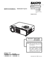
2.4 PSIG Adjustment
1. Receive the 16-step gray scale computer signal with
Computer [Analog RGB]
mode.
2. Enter the service mode.
3. Connect an oscilloscope to test point "
TP3501
" (+) and chassis ground (-).
4. Select item no. "
22
" and adjust the amplitude "a" to be
10.0
±0.1V by changing the
Data value.
5. Select item no. "
23
" and adjust the amplitude "b" to be
3.8
±0.1V by changing the
Data value.
Fig. 3-3
(a)
(b)
Part 3: Adjustment
3-8
Содержание D78-5382
Страница 2: ...CANON Power Projector LV 5200U D78 5382 LV 5200E D78 5383 SERVICE SMANUAL ...
Страница 9: ...Part 1 General Information ...
Страница 25: ...Part 2 Repair Information ...
Страница 45: ...Part 3 Adjustment ...
Страница 65: ...Part 4 Troubleshooting ...
Страница 84: ...Part 4 Troubleshooting 4 19 AD9884AKS A D IC8201 AN5870SB RGB SW IC5201 ...
Страница 87: ...Part 4 Troubleshooting 4 22 FA5502 P F Control IC611 CXD3526GG LCD Driver Timing Generator IC401 ...
Страница 88: ...Part 4 Troubleshooting 4 23 LA7217 Sync Separator IC5361 M62392 D A IC3561 ...
Страница 89: ...Part 4 Troubleshooting 4 24 M62393 D A IC281 IC7801 NJM2284M Switch IC2101 ...
Страница 91: ...Part 4 Troubleshooting 4 26 VPC3230D Video Decoder IC3101 ...
Страница 92: ...Part 5 Parts Catalog ...
Страница 94: ......
Страница 97: ...58 70 63 71 57 60 65 59 64 66 51 55 62 Page 2 CANON REF No LV 5200U D78 5382 LV 5200E D78 5383 ...
Страница 101: ...45 45 45 45 52 52 a 52 Page 4 CANON REF No LV 5200U D78 5382 LV 5200E D78 5383 ...
Страница 105: ...Page6 CANON LV 5200U REF NO D78 5382 LV 5200E D78 5383 A B C A6800 E FUSE LF901 L901 902 L903 LABEL2 ...
Страница 107: ...U 1 U 2 V 1 W X Y Z 1 Page 7 Z 2 CANON REF No LV 5200U D78 5382 LV 5200E D78 5383 ...
Страница 111: ...Part 6 Electrical Diagrams ...