Chapter 16
16-14
When done, store the P-PRINT printout [1] you have
previously generated in the service book, disposing
of the older printout, if any.
(4) Adjustment of ADF stream reading (Make this
adjustment only for the machine with ADF
attached.)
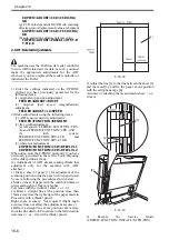
1) Make a sheet of paper [1] for adjustment of the
scanning position using the paper (white paper) used
by users, following the procedures shown below.
á) Make a sheet of paper with the width of 40mm or
wider and height of 50mm or higher.
Tolerance with the width of 14mm: + or - 0.3
á) Draw a straight line at the position more than
15mm away from the right edge of the paper made in
Procedure with a (black) pencil.
Right angle accuracy: Not required (Right angle
accuracy does not affect the adjustment accuracy.)
áB Draw a straight line at the position 14mm away
from the line drawn in Procedure áA to the left
direction (tolerance: + or - 0.3) with a (black) pencil.
F-16-37
2) Adjust the line [1] to the line between the sheet [2]
and the mold [3], and fix the paper at one position
with the cellophane tape [4].
Accuracy of attaching the measurement sheet: + or -
0.3mm
F-16-38
3) Execute the Service Mode
(COPIER>FUNCTION>INSTALL>STPD-POS).
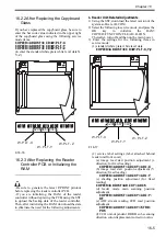
16.6.2 Replacing DC Controller PCB
1)After replacing the DC controller PCB, clear the
memory of the DC controller PCB with the
following service mode.
COPIER > FUNCTION > CLEAR > DC-CON
COPIER>FUNCTION>CLEAR>DC-CON
2) Enter the value written on the service label from
the following service mode.
Laser Main Scanning Writ Start Position
Adjustment
COPIER > ADJUST > LASER > PVE-OFST
Laser Maker Identification
COPIER > ADJUST > LASER > LA-MK-Y/M/C/K
Laser Magnification
COPIER > ADJUST > LASER > LDADJ1-Y/M/C/
K
LDADJ2-Y/M/C/K
LDADJ3-Y/M/C/K
Laser Phase Difference
COPIER > ADJUST > LASER > LDADJ4-Y/M/C/
K
14mm
15mm
or more
[1]
[4]
14mm
[3]
[2]
[1]
Содержание Color imageRUNNER C5180 Series
Страница 22: ...Chapter 1 INTRODUCTION...
Страница 64: ...Chapter 2 INSTALLATION...
Страница 110: ...Chapter 3 BASIC OPERATION...
Страница 119: ...Chapter 4 BASIC OPERATIONS AS A PRINTER...
Страница 129: ...Chapter 5 MAIN CONTROLLER...
Страница 132: ...Chapter 5 5 2 F 5 1 A Reader Unit B DC controller Circuit Board C Printer Unit A B C HDD 1 2 3 3 4 5 6 7 8 9...
Страница 138: ...Chapter 5 5 8 F 5 8 CPU HDD ROM access to the program at time of execution...
Страница 165: ...Chapter 6 ORIGINAL EXPOSURE SYSTEM...
Страница 209: ...Chapter 7 IMAGE PROCESSING SYSTEM...
Страница 210: ...Contents Contents 7 1 Digital Image Processing 7 1 7 1 1 Overview 7 1 7 1 2 Shading Correction 7 1...
Страница 212: ...Chapter LASER EXPOSURE 8...
Страница 239: ...Chapter 9 IMAGE FORMATION...
Страница 324: ...Chapter 10 PICKUP FEEDING SYSTEM...
Страница 355: ...Chapter 10 10 28 F 10 30 F 10 31 9 1 2 3 4 5 1 2 3 4 5 10 thereafter repeats 7 through 10 11 1 2 3 4 5 12 1 2 3 4 5...
Страница 358: ...Chapter 10 10 31 F 10 36 F 10 37 5 1 2 6 1 2 in wait for re pickup point of reversal 9 1 2 3 10 1 2 3...
Страница 435: ...Chapter 11 FIXING SYSTEM...
Страница 460: ...Chapter 11 11 23 F 11 13 SEN3 SEN2 SEN1 SEN2 SEN3 SEN1 SEN2 SEN3 SEN1...
Страница 491: ...Chapter 12 EXTERNALS CONTROLS...
Страница 498: ...Chapter 12 12 5 F 12 2 FM1 FM7 FM9 FM2 FM13 FM14 FM12 FM11 FM10 FM5 FM3 FM4 FM8 FM6...
Страница 512: ...Chapter 12 12 19 2 Remove the check mark from SNMP Status Enabled F 12 10...
Страница 553: ...Chapter 13 MEAP...
Страница 557: ...Chapter 14 RDS...
Страница 569: ...Chapter 15 MAINTENANCE INSPECTION...
Страница 578: ...Chapter 16 STANDARDS ADJUSTMENTS...
Страница 597: ...Chapter 17 CORRECTING FAULTY IMAGES...
Страница 612: ...Chapter 17 17 14 F 17 7 PLG1 ELCB1 SP1 H4 H3 H2 H1 H1 H2 LA1...
Страница 617: ...Chapter 18 SELF DIAGNOSIS...
Страница 644: ...Chapter 19 SERVICE MODE...
Страница 778: ...Chapter 20 UPGRADING...
Страница 823: ...Chapter 21 SERVICE TOOLS...
Страница 824: ...Contents Contents 21 1 Service Tools 21 1 21 1 1 Special Tools 21 1 21 1 2 Solvents and Oils 21 2...
Страница 828: ...APPENDIX...
Страница 851: ......


