


COPYRIGHT © 2000 CANON
COPYRIGHT © 2000 CANON INC.
INC. 2000 2000 2000 2000
2000 2000 2000 2000
CANON NW Mul
CANON NW Multi-PD
ti-PDL P
L P. kit-A1 REV
. kit-A1 REV.0 SEP
.0 SEPT
T. 2000PRINTED I
. 2000PRINTED IN USA
N USA
1
1
CONTENTS
CONTENTS
Contents
Contents
CHAPTER 1 GENERAL DESCRIPTION
CHAPTER 1 GENERAL DESCRIPTION
1.
1. Out
Outlin
line
e of
of the
the Pro
Produc
ductt ...
.......
.......
......
.......
.......
.....
.. 1-1
1-1
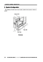
2.
2. Sy
Syst
stem
em Co
Conf
nfig
igur
urat
atio
ion
n ..
....
....
....
....
....
.....
.....
....
....
.... 1-
1-2
2
3.
3. Fea
Featur
tures
es ...
.......
.......
......
......
......
......
......
......
......
.......
.......
......
......
... 1-3
1-3
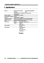
4.
4. Spe
Specif
cifica
icatio
tions
ns ...
......
......
......
......
......
......
.......
.......
......
......
..... 1-4
1-4
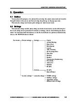
5.
5. Ope
Operat
ration
ion ....
.......
......
.......
.......
......
......
.......
.......
......
......
.......
......
.. 1-5
1-5
5.1
5.1 Ou
Outl
tlin
inee ...
.....
....
....
.....
.....
....
....
....
.....
.....
....
....
....
.....
.....
....
.... 1-
1-5
5
5.2
5.2 Set
Settin
tings......
gs.........
......
.......
.......
.......
.......
......
.......
.......
......
... 1-5
1-5
5.3
5.3 T
Test
est Pri
Printi
nting
ng ...
......
......
.......
.......
......
......
......
.......
......
.. 1-6
1-6
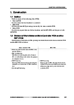
1.
1. Con
Constr
struct
uction
ion ...
.......
.......
.......
.......
......
.......
.......
.......
.......
......
... 2-1
2-1
1.1
1.1 Ou
Outl
tlin
inee ..
....
....
.....
.....
....
....
....
.....
.....
....
....
....
.....
.....
....
....
....
.. 2-
2-1
1
1.2
1.2 Di
Divis
vision
ion of
of W
Work
ork Bet
Betwee
ween M
n Main
ain
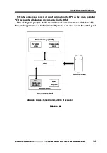
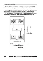
Controller PCB and the RIP1 PCB
Controller PCB and the RIP1 PCB
...................................................
................................................... 2-1
2-1
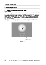
2.
2. Bas
Basic
ic Ope
Operat
ration
ion ...
......
.......
.......
......
......
......
.......
.......
......
... 2-2
2-2
2.1
2.1 Sta
Start-
rt-Up
Up Seq
Seque
uence
nce (ho
(host
st ma
machi
chine)
ne)
...................................................
................................................... 2-2
2-2
2.
2.1.
1.1
1
Ou
Outl
tlin
inee ..
....
.....
.....
....
.....
.....
....
.....
.....
....
.....
.....
....
.... 2-
2-2
2
2.2
2.2 Pr
Prin
inti
ting
ng ...
.....
....
.....
.....
....
.....
.....
....
....
.....
.....
....
.....
.....
....
.... 2-
2-5
5
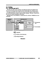
2.
2.2.
2.1
1
Pr
Proc
oces
essi
sing
ng by
by th
the P
e PC
C ..
....
....
....
....
.... 2-
2-5
5
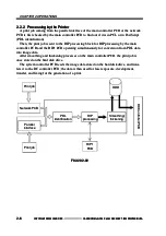
2.
2.2.
2.2
2
Pr
Proc
oces
essi
sing
ng by
by th
the P
e Pri
rint
nter
er ..
....
.... 2-
2-6
6
2.3
2.3 T
Tra
rans
nsfe
ferr
rrin
ing
g Pr
Prin
int
t Da
Data
ta ..
....
....
....
....
.....
..... 2-
2-7
7
2.
2.3.
3.1
1
Co
Conn
nnec
ecti
ting
ng th
the P
e Par
aral
alle
lel P
l Por
ortt
.............................................
............................................. 2-7
2-7
2.
2.3.
3.2
2
Co
Conn
nnec
ecti
ting
ng to
to th
the N
e Net
etw
wor
ork
k ..
.. 2-
2-8
8
2.4
2.4 Pr
Proc
oces
essi
sing
ng Pr
Prin
int J
t Job
obss ..
....
.....
.....
....
....
....
.. 2-
2-16
16
2
2.4
.4.1
.1
Im
Imaage
ge Da
Data
ta Ou
Outp
tput
ut B
Blo
lock
ck ..
.. 2
2-1
-16
6
2.
2.4.
4.2
2
Pr
Proc
oces
essi
sing
ng by
by th
the H
e Hos
ost M
t Mac
achi
hine
ne
...........................................
........................................... 2-16
2-16
2.5
2.5 Ne
New F
w Fun
unct
ctio
ions
ns ..
....
.....
.....
....
....
.....
.....
....
....
.....
... 2-
2-17
17
2.
2.5.
5.1
1
Se
Secu
cure
red Pr
d Prin
inti
ting
ng ..
....
....
....
....
....
....
....
.. 2-
2-17
17
2.
2.5.
5.2
2
Bu
Bull
llet
etin B
in Boa
oard
rd ..
....
....
....
....
....
....
....
....
.... 2-
2-17
17
2.
2.5.
5.3
3
Po
Port
rt 91
9100
00 pr
prin
inti
ting....
ng......
....
.....
.....
.... 2-
2-18
18
2.
2.5.
5.4
4
ID
ID M
Man
anaag
gem
emen
ent b
t by G
y Gro
rou
up
p ..
.. 2-
2-18
18
2.
2.5.
5.5
5
IP
IPP
P ...
.....
.....
.....
.....
.....
....
.....
.....
.....
.....
.....
.....
.....
.....
.. 2-
2-19
19
1.
1. Out
Outlin
linee ....
.......
......
.......
.......
......
......
.......
.......
......
.......
.......
......
......
... 3-1
3-1
2.
2. Pri
Printe
nter
r Dri
Drive
vers
rs ...
......
......
.......
.......
......
.......
.......
......
......
.....
.. 3-2
3-2
3.
3. Uti
Utilit
lities
ies ...
......
.......
.......
......
......
......
......
......
......
......
.......
.......
......
..... 3-3
3-3
3.1
3.1 Ne
NetS
tSpo
pott ..
....
....
.....
.....
....
....
.....
.....
....
....
.....
.....
....
....
.....
.....
.. 3-
3-3
3
3.2
3.2 JB
JBIG
IG V
Vie
iewe
werr ..
.....
.....
....
....
....
....
.....
.....
....
....
....
....
.....
... 3-
3-3
3
CHAPTER 3 USER SOFTWARE
CHAPTER 3 USER SOFTWARE
CHAP
CHAPTER 4 INS
TER 4 INST
TALL
ALLA
ATIO
TION
N
1.
1. Out
Outlin
linee ....
.......
......
.......
.......
......
......
.......
.......
......
......
.......
.......
......
... 4-1
4-1
2.
2. Po
Poin
ints t
ts to No
o Note fo
te for In
r Inst
stal
alla
lati
tion
on ..
....
....
....
....
.. 4-
4-2
2
2.1
2.1 In
Inst
stal
alla
lati
tion
on Pr
Proc
oced
edur
uree ..
....
....
....
.....
.....
....
.... 4-
4-2
2
2.2
2.2 Us
User
er So
Soft
ftwa
ware
re CD
CD-R
-ROM
OM ...
.....
....
....
....
.... 4-
4-2
2
3.
3. In
Inst
stal
alla
lati
tion
on Pr
Proc
oced
edur
uree ...
.....
....
....
....
.....
.....
....
....
....
.. 4-
4-3
3
3.
3.1
1 Ch
Chec
ecki
king th
ng the At
e Atta
tach
chme
ment
ntss ..
....
....
....
.... 4-
4-3
3
3.2
3.2 In
Inst
stal
alla
lati
tion
on ..
....
....
....
.....
.....
....
....
....
....
.....
.....
....
....
....
.... 4-
4-4
4
4.
4. Co
Conn
nnec
ecti
ting
ng to t
to the N
he Net
etwo
work
rk ..
....
....
.....
.....
....
.... 4-
4-6
6
5.
5. Ch
Chec
ecki
king the Co
ng the Conn
nnec
ecti
tion
on ..
....
....
....
....
....
....
.....
... 4-
4-7
7
5.1
5.1 Us
Usin
ing
g PI
PING
NG ..
.....
.....
....
....
....
....
.....
.....
....
....
....
.....
.....
.. 4-
4-7
7
5.2
5.2 Ma
Maki
king
ng a C
a Che
heck
ck Us
Usin
ing a
g a Re
Remo
mote
te
Host Addr
Host Address
ess ......
.............
.............
.............
...........
.... 4-7
4-7
CHAPTE
CHAPTER 2 OPE
R 2 OPERA
RATIONS
TIONS


