background image

05

ASSEMBLY

STEP 1.

Attach Quick Release Knob (#06) and Quick Release Pop Knob (#07) 

and tighten.

Insert the Lower Upright Tube (#09) into the Upper Upright Tube (#08)

and secure it with two Head screws  (#12).

12

07

06

08

09

Содержание 10-0716

Страница 1: ...Exer II The specification of this product may vary from this photo subject to change without notice PT21000 Owner s Manual...

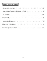
Страница 2: ...01 Safety Instructions 2 3 Parts List 8 Assembly Diagram 9 Assembly Parts Hardware Pack 4 Assembly 5 7 Electronic Monitor 10 Operating Instruction 11 TABLE OF CONTENTS...

Страница 3: ...mally Handle unit with care Inappropriate handling of the unit may adversely affect its characteristics DO NOT permit any foreign materials or liquids to enter the unit Take care to prevent any foreig...

Страница 4: ...s unit only for its intended purpose as described in this manual This unit should only be used by one person at a time Do not put hands feet or any foreign objects on or near this unit when in use by...

Страница 5: ...4 x 2 4pcs 18 Wall mount 4pcs 17 16 Open End Wrench Double Open End Wrench 1 5v AA Battery 1Pc Allen wrench Socket Head Screw M8x50L 4pcs Flat Washer 8 5x 16x1 5t 4pcs Nylon nut M8 4pcs 13 14 15 12 He...

Страница 6: ...ASSEMBLY STEP 1 Attach Quick Release Knob 06 and Quick Release Pop Knob 07 and tighten Insert the Lower Upright Tube 09 into the Upper Upright Tube 08 and secure it with two Head screws 12 12 07 06 08...

Страница 7: ...06 STEP 2 Attach the Main Unit to the Main Frame Mounting 11 Then secure it with four M8x50L Socket screws 13 four Flat washers 14 and four M8 Nylon nut 15 13 15 14 14 11 11...

Страница 8: ...07 STEP 3 Secure the Main Unit to a level wall board with four Hex Head screw 16 four Flat washers 17 and four Wall mounts 18 Attach the Pedals 20 to the Crank 03 and tighten them 16 17 18 03 20 20...

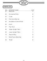
Страница 9: ...Q TY 01 Main Unit 02 Decoration Plate 03 Crank 04 Electronic Monitor 05 Resistance Control Knob 06 Knob 07 Pop Knob 08 Upper Upright Tube 09 Lower Upright Tube 10 Square Plug 11 Main Frame Mounting 20...

Страница 10: ...09 ASSEMBLY DIAGRAM 01 02 03 04 05 06 07 11 10 08 09 11 10 20 20...

Страница 11: ...E A GOOD RESULT 4 BATTERY SPEC 1 5V AA 1PC ELECTRONIC MONITOR FUNCTION BUTTON MODE RESET PRESS TO SELECT FUNCTIONS RESET OR HOLD ON CAN BE TOTAL RESET FOR ALL FUNCTION VALUES FUNCTIONS STOP WHEN STOP...

Страница 12: ...is to control the amount of resistance applied during exercise Turn the Resistance Control Knob clockwise for a more difficult workout and count clockwise for a less difficult workout It is recommend...

Отзывы: