M U L T I - P U R P O S E A P P L I C A T I O N B O A R D S F O R D M S - 2 0 M E T E R S
DMS-EB2
MPM_DMS-EB2_D00
Page 2 of 4
D I G I T A L P A N E L M E T E R S
www.cd4power.com
TECHNICAL NOTES
APPLICATIONS
1. LCD Backlighting:
To backlight a DMS-20LCD meter, connect J1, pin
3 (TEST/HOLD IN) to J1, pin 6 (GND). This allows for external control,
via a switch, of the backlight feature. The switch should be rated for low
voltage operation at 35mA.
2. 9V LCD Meters:
DMS-20LCD-X-9 meters cannot be used in a single-
ended configuration, i.e., with (–) IN LO tied to GND. On these models,
both (–) IN LO and (+) IN HI have to be a minimum of 1.5V above and
1.5V below J1 pins 6 and 5, respectively. To operate from a 9V or 12V
battery with (–) IN LO tied to GND, use a 5V-powered meter (DMS-
20LCD-X-5), install U1 (LM7805CT) and open SG4.
3. Input Resistor Dividers:
Always use 1%, or better, metal-film resistors
for R1 and R2, and also make sure their power and voltage ratings are
adequate for the given application.
4. Using U1 (LM7805CT):
The input power range specified in the Battery
Operation section is rated conservatively assuming a 100mA LED meter
or a 35mA backlit LCD meter. If a non-backlit LCD model or the low-
power LED model is used, the input voltage range can be extended up to
32Vdc.
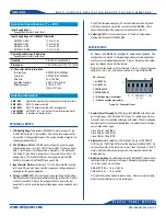
As shipped, the DMS-EB2 is configured for single-ended operation. This
configuration is preferred for simple voltage measurements and will gen-
erally cover most standard applications. Figure 1 indicates which solder
gaps are shipped closed from the factory.
Simply solder the board onto the meter (pin 1 to pin 1), connect the power
supply to J1, pin 5 (+V) and the power return to J1, pin 6 (GROUND).
1. Decimal Point Placement:
DATEL ships the DMS-EB2 with all decimal
point solder gaps (SG1, SG2 and SG3) open. To enable a specific deci-
mal point, close its respective solder gap with solder. When re-assigning
decimal places for subsequent applications, remember to unsolder previ-
ously closed solder gaps.
Close SG1 for 1.999 (DP1)
Close SG2 for 19.99 (DP2)
Close SG3 for 199.9 (DP3)
2. Display Test
(Not Available on LCD Models)
:
Tie pin 4 (TEST/HOLD
OUT) to pin 3 (TEST/HOLD IN) to test the display of the DMS-20PC. Do
not leave the meter in the test mode for more than 10 seconds. On LED
meters with the HOLD option, tying pins 3 and 4 together freezes the
display reading.
3. Battery Operation:
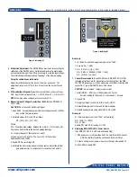
Open SG4 and install U1 (LM7805CT) with its metal
tab facing to the left as shown in Figure 3. Allowable input power ranges
(J1, pins 5 and 6) are as follows:
DMS-20PC-X-XS +7.5 to +12.6Vdc
DMS-20PC-X-XL +7.5 to +32Vdc
C2 (10µF/35V) can be added to reduce noise. Observe correct polarity.
Refer to Technical Note 4 for more information.
Figure 2. J1 Connector Pinout
Pin Function
1 (+) INPUT HI
2 (–) INPUT LO
3 TEST/HOLD IN
4 TEST/HOLD OUT
5 +V (Positive power connection)
6 –V (Ground, negative power return)
1
2
3
4
5
6
�
�
+V
HI�
(+)
LO�
(–)
TST/�
HOLD�
IN
TST/�
HOLD�
OUT
–V�
GND
J1
DMS-EB2
Application board with mating connector and terminals
DMS-BZL3
DMS-20 bezel assembly
DMS-BZL4
DMS-20 bezel assembly with sealing gasket
39-0304000
LM7805CT (U1), +5V-output, three-terminal regulator
39-2359625
6-position pc-board socket
Input Supply Range
See applicable meter's data sheet
Input Supply Range U1 (LM7805CT) Installed:
DMS-20PC-X-XS
+7.5 to +12.6V
DMS-20PC-X-XL
+7.5 to +32.0V
DMS-20LCD-X-5
+7.5 to +32.0V
DMS-20LCD-X-5B
+7.5 to +12.6V
Operating and Storage Temperature
See applicable meter's data sheet
Humidity
0 to 95%, non-condensing
Dimensions
1.25" (31.8mm)L x 0.75" (19.1mm)H
J1 Connector & Wire Information
Terminal Type
DATEL P/N 39-2099090
Crimp Tool
DATEL P/N 39-2099000
Wire Size
22 to 26 AWG
Insulation Diameter
0.062" (1.57mm) max.
Stripping Length
0.100" to 0.125"
(2.54 to 3.17mm)
Ordering Information
Functional Specifications (T
A
= 25ºC)
A 10µF/35V tantalum capacitor (C2 on schematic) should be installed
with the polarized end next to the + symbol on the DMS-EB2. This is
especially important if the power source is located far from U1.
5. Soldering:
DATEL recommends the use of "no-clean" solders when
making modifications to the DMS-EB2.


