background image

6226 Netherhart Road, Mississauga, Ontario, L5T 1B7 

99-0079 
Rev. 0.3 


INSTALLATION OPERATION 

AND SERVICE MANUAL 


GAS FIRED RESIDENTIAL AND COMMERCIAL STAINLESS 

STEEL TANK HEATERS


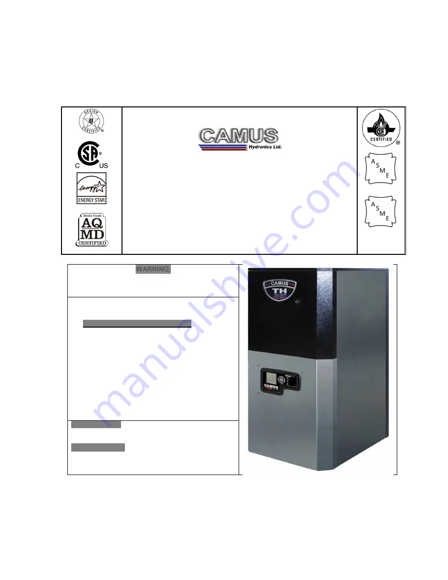
TH SERIES 


HOT WATER SUPPLY 


Models

;

 TH082 ,102, 152, 202, 252,  

292, 392, 502 


        H 


HLW 


WARNING: 

If the information in these instructions is not followed 
exactly, a fire or explosion may result causing property 
damage, personal injury or death 


Do not store or use gasoline or other flammable 
vapours and liquids in the vicinity of this or any 
other appliance. 
WHAT TO DO IF YOU SMELL GAS 

o


Do not try to light any appliance, 

o


Do not touch any electrical switch; do not 
use any phone in your building, 

o


Immediately call your gas supplier from a 
neighbour’s phone. Follow the gas 
supplier’s instructions, 

o


If you cannot reach your gas supplier, call 
the fire department. 

Qualified installer, service agency or the 
gas supplier must perform installation and 
service. 

 
To the Installer: After installation, these instructions 
must be given to the end user or left on or near the 
appliance. 
To the End User: This booklet contains important 
information about this appliance. Retain for future 
reference.  

CAMUS   HYDRONICS   LTD. 

Содержание TH082

Страница 1: ...ity of this or any other appliance WHAT TO DO IF YOU SMELL GAS o Do not try to light any appliance o Do not touch any electrical switch do not use any phone in your building o Immediately call your ga...

Страница 2: ......

Страница 3: ...ERMINATION AND AIR INLET CLEARANCES 9 2 5 1 Sidewall Venting 9 2 5 2 Sidewall Air Inlet 10 2 5 3 Sidewall Concentric Vent Air 10 2 6 Vertical Direct Venting 10 PART 3 GAS CONNECTION 12 3 1 GAS CONNECT...

Страница 4: ...MENT 41 10 4 1 Condensate Volume 41 10 5 IGNITER AND FLAME SENSOR ELECTRODES 42 10 6 CHECK IGNITER GROUND WIRING 42 10 7 BURNER MAINTENANCE 42 10 7 1 Burner Removal and Cleaning 42 10 8 REMOVAL OF COM...

Страница 5: ...arrier 1 4 DISPLAY UNIT The display unit will indicate status and will display selected temperature Refer to Part 8 TH Control Panel which provides details to modes and error codes displayed on the ap...

Страница 6: ...n anything against it store trash or debris near it stand on it or in any way block the flow of fresh air to appliance UNDER NO CIRCUMSTANCES may flammable materials such as gasoline or paint thinner...

Страница 7: ...ll soot or other obstructions from the chimney and flue which might impede draft action Replace any damaged or deteriorated parts of the venting system A qualified service technician should follow thi...

Страница 8: ...e designed for indoor installation Indoor Models must be installed indoors where it is protected from exposure to wind rain and weather The appliance designed for outdoor installation Outdoor Models m...

Страница 9: ...im F in Dim G in Dim H in Equivalent Length of Vent Air Intake Pipes at Recommended Diameter in Water Conn at Boiler in NPT Gas Conn at Boiler in NPT Category IV CAT II Comb Vents Over 25 and up to 10...

Страница 10: ...r adequate operation All installations must allow sufficient space for servicing the vent connections water pipe connections circulating pump bypass piping and other auxiliary equipment as well as the...

Страница 11: ...to the vent terminal The weight of the venting system must not rest on the unit Adequate support of the venting system must be provided in compliance with local codes and other applicable codes All co...

Страница 12: ...vertical or horizontal Outside air ducted to jacket flange Indoor Air Table 6 Required Vent and Air Inlet Diameters Equivalent Length of Vent Air Intake Pipes at Recommended Diameter Input BTU hr Cat...

Страница 13: ...of the vent terminal shall be located at least 3 feet 1m above grade or above normal snow levels In all cases the appliance shall be installed in accordance with local codes 3 The TH can vent up to 10...

Страница 14: ...te below a forced air inlet at any distance 4 The termination cannot terminate below grade Position the termination where vapours will not damage walls or plants or may be otherwise objectionable 5 Th...

Страница 15: ...east 3 feet 1m above grade or above normal snow levels In all cases the appliance shall be installed in accordance with local codes 3 The termination MUST NOT terminate below a forced air inlet at any...

Страница 16: ...liance connection Installation of a union at the appliance gas line connection is required for ease of service and removal of the gas train Install a manual main gas shutoff valve outside of the appli...

Страница 17: ...rve burner response The burner should ignite promptly Flame profile should be stable see section 10 2 Visually Check Main Burner Flames Turn system off and allow burner to cool then cycle burner again...

Страница 18: ...e burner Airborne contaminants such as dust dirt concrete dust or dry wall dust can be drawn into the burner with the combustion air and block the burner surface area DO NOT operate this appliance dur...

Страница 19: ...nt number of straight feet of pipe for each valve and fitting in the connecting piping must be considered to properly arrive at the total equivalent feet of straight pipe in the field installed piping...

Страница 20: ...m 120VAC 60Hz single phase 15A circuit is required for the TH models TH 082 through TH 502 The appliance when installed must be electrically grounded in accordance with the requirements of the authori...

Страница 21: ...fault is corrected the boiler will automatically return to normal operating state 5 4 ERROR TABLE The following tables provide a description of all the possible errors with the TH boiler Errors can be...

Страница 22: ...circulate until the pump overrun timer is satisfied Frost Protection To prevent freezing of the heat exchanger the on board pump is turned on if the DHW temperature is below 45 o F The on board pump...

Страница 23: ...te of the appliance 7 4 GAS VALVE Figure 19 Venturi and Gas Valve Arrangement The Gas Valve supplied with the TH is a combined valve venturi assembly A servo pressure regulator is incorporated into th...

Страница 24: ...text on the LCD will be shown for 2 seconds followed by the software version number for an additional 2 seconds The Version relates to the version of software uploaded onto the boiler control The disp...

Страница 25: ...a Temperature Display delta T temperature Outlet Temperature Inlet Temperature DHW Temperature Display DHW temperature When UP DOWN is pressed this allows the DHW setpoint temperature to be changed Ra...

Страница 26: ...degrees Fahrenheit or degrees Celcius Range o F o C LBTHODLOD not used LBT Low Boiler Reset Temperature Range Off On 32 to 230 o F 0 110 o C Default Off HOD High Outdoor Reset Temperature Range Off O...

Страница 27: ...ot require manual intervention The last received alert code is displayed in User mode To clear the alert code press the Reset button Refer to Table 13 in Section 5 4 2 for more details Alerts are auto...

Страница 28: ...emperature display After 5 minutes of inactivity or when the Done button is pressed the TH returns to normal operation Maximum Firing Rate Max icon is flashing and the Diag icon is solid The heater wi...

Страница 29: ...use of the boiler User Access to general boiler and display settings and adjustments to the central heating and domestic hot water setpoint Installer Access to all user parameters and allows for chang...

Страница 30: ...er operation DHW Pump Pump C Additional contact rated for 1 6hp Sequence of Operation Pump A is energized on DHW Interlock Flow switch LWCO if equipped Blocked flue switch N C Low gas switch 4 5 w c N...

Страница 31: ...CAL 2 Press and select Login 3 Select Advanced Setup 4 Select DHW Config Inlet Sensor operation 5 Select Demand switch Sensor only and Press 6 Select Mod sensor Inlet and Press go to step 7 DHW Stat o...

Страница 32: ...es in LOCAL 2 Press and select Login 3 Select Advanced Setup 4 Select Burner Control Ignition 5 Select Adjustable lightoff rate and enter desired lightoff rate using 5 way control and press Adjust sta...

Страница 33: ...iption Programming Instructions To view burner run time pump cycles for maintenance and service purposes 1 Place both toggle switches in LOCAL 2 Press and select Login 3 Select Advanced Setup 4 Select...

Страница 34: ...ontrol Panel will be required to restart the ignition sequence The boiler has failed to ignite the burner after 5 unsuccessful attempts Verify that all air has been purged from gas line Inspect spark...

Страница 35: ...ler if necessary Noisy Operation Supply Gas Issue Refer to Part 3 Gas Connection in this manual Natural Gas Pressure should read between 3 w c and 14 w c L P Gas Pressure should be at 11 w c Air Gas M...

Страница 36: ...ceeded the maximum temperature allowed Measure the resistance of the flue sensor at room temperature it should be approximately 10k The supply outlet temperature has exceeded the setpoint temperature...

Страница 37: ...turn at a time NO Verify gas valve is being powered by ignition control Check ignition speed is between 2500 to 3000 RPM using System Monitor NO Adjust ignition speed to 3000 RPM YES YES Burner light...

Страница 38: ...tripped optional To identify the safety that is open set the multimeter to Vac and measure the voltage from one contact to ground The contacts produce a 24Vac when the circuit is closed Is vent and o...

Страница 39: ...to ground The contacts produce a 24Vac when the circuit is closed Is pump powered NO Check pump wiring and pump delay relay YES Use meter to verify amperage draw on pump and verify it with rating labe...

Страница 40: ...150 o F is selected and PVC venting is used the setpoint must be reduced to below 150 o F to avoid nuisance flame failures If a setpoint greater than 150 o F is required venting with CPVC AL29 4C 316...

Страница 41: ...rod Is Flame sensor plug secure NO Fasten flame sensor plug securely to flame sensor wire and check for corrosion deposits at wire terminals YES Check continuity of flame sensor wire from flame sensor...

Страница 42: ...Figure 25 Venturi Gas Valve Assembly To adjust the high fire setting on standard display Press and hold the Next button for 3 seconds to enter the diagnostic menu on the TH Control Panel Press Next u...

Страница 43: ...ollowing screen appears Figure 30 Low Fire Adjustment Screen To return to normal operation press Done To adjust the low fire setting on the upgraded display 1 Press the button 2 Select Test and press...

Страница 44: ...NINGS in this manual are complied with To service or adjust this appliance it is imperative that the serviceman utilize a combustion analyzer to read CO2 and CO according to Camus Hydronics recommenda...

Страница 45: ...NOTE All gaskets on disassembled components must be replaced with new gaskets sealant on re assembly if required Gasket kits are available from the factory CAUTION When the vent system is disconnecte...

Страница 46: ...o the fan inlet Disconnect the fan motor power wires at the harness Remove the direct spark igniter and the flame sensor Remove the three 3 T 25 screws holding the front burner flange in place to gain...

Страница 47: ...supplied to 24VAC components may cause operational problems 10 11 COMBUSTIBLE MATERIALS CAUTION Keep appliance clear from combustible materials do not store GASOLINE and other flammable vapors and liq...

Страница 48: ...h fresh water until the water begins to flow out of drain 5 Re install the lid and hold down screw on the condensate collection box WARNING The condensate collection box must be filled with water to p...

Страница 49: ...ater on and allow time for the temperature to stabilize Check the temperature rise when the burner is firing at 100 of rated input 4 Compare the temperature rise on the Control Panel with the required...

Страница 50: ...46 11 9 IGNITION CYCLE The ignition cycle is shown in the table below The values are the default factory settings Figure 36 TH Ignition Cycle...

Страница 51: ...Figure 37 Dedicated DHW Suggested Piping Arrangement Figure 38 Combination Application Suggested Piping Arrangement Note Cold water piping should be below hot water connections to prevent heat migrat...

Страница 52: ...48 PART 13 EXPLODED VIEW PARTS LIST...

Страница 53: ...Air Inlet Adapter 14 0379 X X X X X X X 44 0009 X 9 Transition Arm GM20 70 020 01 X X X X X X X GM10 15 997 03 10 Venturi 459000 444 003 X X 459000 444 001 X 459000 446 051 X X 45900450 010 X X VMU30...

Страница 54: ...X X X X 32 HX Support 14 5632 X X X 14 5612 X X 33 Flame Sensor GM10 35 109 01 X 34 Igniter GM10 35 108 01 X 35 Current Transformer MCSS A U X 36 Right Bracket 14 5513 20 25 X 37 Left Bracket 14 5410...

Страница 55: ...r X 53 Metal Latch 6521 00 0551 YT X 54 Strike 7800 02 55 On Off Switch C6000ALBBCHLI X 56 Standard Display S7910B1006 X 57 Upgraded Display DSP49G2094 X 58 Gas Valve Relay T9CP1A54 24 X 59 TH Wire Ha...

Страница 56: ...52 PART 14 ELECTRICAL DIAGRAMS 14 1 TH 82 502 INTERNALWIRING DIAGRAM...

Страница 57: ...nd 2 Display Data Receive 3 Display Common J4 24VAC Power 1 9 Not Used 10 24VAC 11 Not Used 12 Ground J5 Gas Valve Safety String 1 Safety String Return 2 Gas Valve 24VAC 3 7 Not Used J6 Safety Annunci...

Страница 58: ...d appliance temperature or operating at temperatures exceeding 210o F BURNER If within FIVE years after initial installation of the appliance a burner shall prove upon examination by Camus to be defec...

Страница 59: ...uilt water heaters and heating boilers as well as a into every single unit For more information supplier of specialty HVAC products Our service line is open 24 hours 7 days a week on our innovative pr...

Отзывы: