2. Default settings
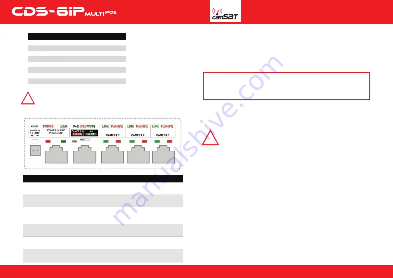
3. Description of the connectors and LEDs
4. Preparing for operation
CDS-6IPMulti device can be connected to the power supply in two ways
Connect the radio module to the LAN adapter with the computer set
IP address of the family 192.168.1.XX. (Eg. 192.168.1.99)
6. Necessary configuration settings - required:
a) Log on to the radio module CDS-6IPMulti (default: 192.168.1.1,
Username: CAMSAT, Password: CAMSAT).
b) Set the destination IP address of the radio module.
c) Set the mode Master (Receiver-Recorder) or slave (transmitter - camera).
d) In the receiver (Master) set the no of target operating channel. It is recommended
to choose a specific number of free channel permanently. AUTO DFS function
(automatic channel selection) starts by selecting the AUTO mode in the "Band" and
the AUTO in "Channel” position.
e) In the transmitter (Slave), press the Scan Masters to find names of radio link SSID
of a given receiver. Select the name of the link SSID and press Connect.
Repeat this step for all transmitters (Slave) to be connected to the receiver (Master)
f) correctly connected transmitters should be visible in the list of linked devices tab
in System Information / Wireless clients
g) In the transmitters set the real distance between the transmitter and receiver.
In the receiver, set the distance of the furthest transmitter.
h) Check the connection between the transmitter and the receiver in the tab,
cameras and DVR by PING.
QUICK START
Option 1 - directly from the power supply 12-48V.
Option 2 - CDS-6IPMulti powered from adapter PoE48V.
DESCRIPTION OF CONNECTORS AND LED INDICATORS
PO
WER IN 12-48V -
input DC or AC (the red
POWER
LED indicates the appearance
of voltage on the connector)
PO
WER IN 48V
- power supply input used only to power the device with another switch or
PoE power supply (the red
POWER
LED indicates the appearance of voltage on the connector)
CAMERA 4/LAN – LAN port to power IP camera (P
oE 48V) or device configu
ration.
PoE voltage on output is controlled by above switch (the value of voltage is shown by
red-green LED
PoE ON
/
PoE OFF
; blinking
LINK
diode shows data transfer status)
CAMERA 3 – LAN port to power the IP camera (
PoE 48V
) ((the red P
O
WER LED indicates
the appearance of voltage on the connect
or; blinking
LINK
diode shows data transfer status)
CAMERA 2 – LAN port to power the IP camera (
PoE 48V
) ((the red P
O
WER LED indicates
the appearance of voltage on the connect
or; blinking
LINK
diode shows data transfer status)
CAMERA 1 – LAN port to power the IP camera (
PoE 48V
) (the red POWER LED indicates
the appearance of voltage on the connect
or; blinking
LINK
diode shows data transfer status)
5. Connecting to a computer
Parameter
Username
Password
Name of device
Working mode
IP address
Subnet mask
Gateway
Country/Region
Channel number
camsat
camsat
CDS-6IPeco
Video Bridge
192.168.1.1
255.255.255.0
0.0.0.0
ETSI/EU
Auto (DFS)
Default factory settings
WARNING
Before connecting the computer to the CAMERA 4 / LAN switch off
PoE voltage of 48V with the switch placed beside.
48V voltage can damage the non-compatible devices!
www.camsat-cctv.com
Full instructions can be found at:
http://camsat-cctv.com/cds-6ipmulti
Full instructions can be found at:
http://camsat-cctv.com/cds-6ipmulti
2
3
Do not use AUTO
channel settings. Be sure to select the channel number
on a permanent according to the current network bandwidth consumption.
Warning
!
Note: The device manufacturer is not responsible for the devices that are not properly
protected and for related damage of the equipment and other network infrastructure
Warning
!


