SDM-CVO4 4-Channel Current/Voltage Output Module
13
7.2.4 Output Terminal Connectors
The output connections use 4-way, screw terminal fixings. These can be
unplugged for ease of wiring, if required.
7.3 Output Mode Setting
An internal jumper sets the output mode for each SDM-CVO4 channel.
Voltage and current output modes are available. Open the case to change the
mode settings. To do this, first disconnect the device from any source or power,
unplug the connectors to disconnect the output connections, then remove the
four larger screws from the face of the case. Lay the unit on a flat surface, take
anti-static precautions, and lift the top half of the case to expose the circuit
board.
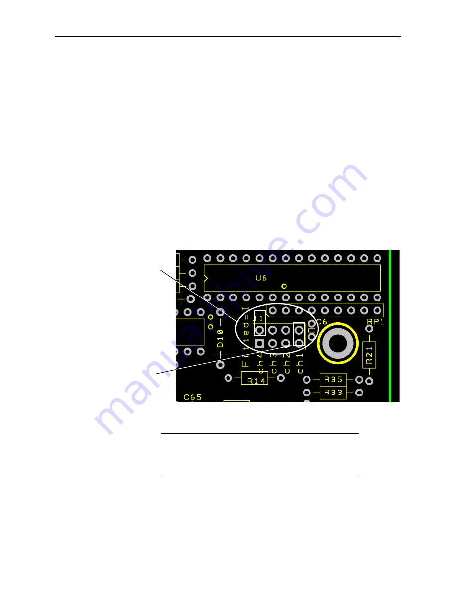
shows the jumper blocks that control the output mode. To operate
in current mode, install the channel jumper between the two jumper pins, as
shown. If operating in voltage mode, the jumper should not bridge any two
pins, but may be stored, if required, by fitting it to just one of the pins, leaving
the other half unconnected.
FIGURE 7-4. Location of Jumpers on Circuit Board
Do not store the jumpers between any other pins in the block
as this may switch the module into a factory calibration
mode, which may result in abnormal operation and change
of output accuracy.
The data logger program can override jumper settings (see Section
(p. 16)
).
CAUTION
Select channel(s) by
fitting jumper (s)
between appropriate
terminals. (Current
mode only.) Jumper
shown fitted to enable
Channel 4.
Jumper shown fitted
in the unconnected
stored position.


