


MET ONE 034A-L WINDSET
8
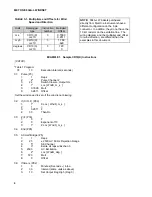
-Input Locations-
1 WndS_m_s
2 WndD_deg
*
Proper entries will vary with program and datalogger
channel and input location assignments.
**
On the 21X use the 5000 mV input range and the
a 5000 mV excitation voltage.
***
Average wind speed, average unit vector wind direction,
standard deviation of unit vector wind direction
8. WIND DIRECTION MEASUREMENT
THEORY
It is not necessary to understand the concepts
in this section for the general operation of the
034A-L Windset with Campbell Scientific’s
datalogger.
The 034A-L Windsets purchased from
Campbell Scientific have a 10 k
Ω
resistor on
the excitation line. This resistor prevents
erroneous measurements when the
potentiometer shorts to ground as the wind
direction crosses over from the west side of
north to the east side of north.
FIGURE 8-1. 034A-L Potentiometer in a Half
Bridge Circuit
8.1 AC HALF BRIDGE, INSTRUCTION 5
Instruction 5 outputs a precise 2500 mV AC
excitation (5000 mV AC excitation with the 21X)
and measures the voltage between the wiper
and analog ground, V
s
. The resistance between
the wiper and analog ground, R
s
, and V
s
varies
with wind direction. Instruction 5 outputs the
ratio of the measured voltage to the excitation
voltage (V
s
/
V
x
). This ratio is related to
resistance as shown below:
(
)
V V
R
R
R
R
R
K
s
x
s
f
t
s
s
=
+
+
=
20
Ω
The maximum value that R
s
will reach is 10 k
Ω
,
just before it crosses over from the west side of
north to the east side of north. V
s
/
V
x
reaches
its maximum value of 0.5 mV/mV at 360
degrees. Thus, the multiplier is 720 degrees.
Since the datalogger outputs the ratio V
s
/
V
x
,
the multiplier is the same for both the CR10(X)
and 21X dataloggers, even though they use a
different excitation voltage. See Section 13.5 in
the datalogger manual from more information
on the bridge measurements.
8.2 DC HALF BRIDGE, INSTRUCTION P4
Instruction 4 outputs a precise 2500 mV
excitation (5000 mV excitation with the 21X)
and measures the voltage between the wiper
and analog ground, V
s
. The resistance between
the wiper and analog ground, R
s
, and V
s
varies
with wind direction. Instruction 4 outputs the
measured voltage, V
s
. This measured voltage
is related to resistance as shown below:
(
)
V
V
R
R
R
R
V
R
K
s
x
s
f
t
s
x
s
=
⋅
+
+
=
⋅
20
Ω
The maximum value that R
s
will reach is 10 k
Ω
just before it crosses over from the west side of
north to the east side of north. V
s
reaches its
maximum value of 1250 mV for the CR10(X) and
2500 mV for the 21X at 360 degrees. Thus, the
multiplier is 0.144 degrees/mV for the CR10(X)
and 0.288 degrees/mV for the 21X. See Section
13.5 in the datalogger manual from more
information on the bridge measurements
9. REFERENCES
The following references give detailed
information on siting wind speed and wind
direction sensors.
EPA, 1989:
Quality Assurance Handbook for
Air Pollution Measurements System
, Office of
Содержание Met One 034A-L
Страница 14: ...This is a blank page ...
Страница 15: ...This is a blank page ...


