INSTRUCTION MANUAL
Met One 034A-L Windset
Revision: 7/97
C o p y r i g h t ( c ) 1 9 8 0 - 1 9 9 7
C a m p b e l l S c i e n t i f i c , I n c .
Страница 1: ...INSTRUCTION MANUAL Met One 034A L Windset Revision 7 97 C o p y r i g h t c 1 9 8 0 1 9 9 7 C a m p b e l l S c i e n t i f i c I n c ...
Страница 2: ...her warranties expressed or implied including warranties of merchantability or fitness for a particular purpose CAMPBELL SCIENTIFIC INC is not liable for special indirect incidental or consequential damages Products may not be returned without prior authorization The following contact information is for US and International customers residing in countries served by Campbell Scientific Inc directly...
Страница 3: ...3 6 Sensor Maintenance 6 7 Long Lead Lengths 6 8 Wind Direction Measurement Theory 8 8 1 AC Half Bridge P5 8 8 2 DC Half Bridge P4 8 9 References 8 Appendix A Wind Direction Sensor Orientation A 1 A 1 Determining True North and Sensor Orientation A 1 A 2 Prompts from GEOMAG A 2 Figures 3 1 034A L Mounted on a 019ALU Horizontal Crossarm 2 4 1 034A L Windset Wiring Diagram 3 8 1 034A L Potentiometer...
Страница 4: ...Subtracted from 0 to Get True North A 2 A 3 Declination Angles West of True North Are Added to 0 to Get True North A 3 Table 5 1 Multipliers and Offsets for Wind Speed and Direction 4 7 1 Multiplier and Offset for Wind Direction when using Lead Lengths Greater than 200 Feet 6 ...
Страница 5: ...e its use inside buildings 3 INSTALLATION 3 1 SITING Locate wind sensors away from obstructions e g trees and building As a general rule of thumb there should be a horizontal distance of at least ten times the height of the obstruction between the windset and the obstruction If it is necessary to mount the sensors on the roof of a building the height of the sensors above the roof should be at leas...
Страница 6: ... to the datalogger for the 034A L are shown in Figure 4 1 The wind speed is measured by a pulse input channel The wind direction is measured by a single ended analog input channel Connect the red lead to a pulse input channel wind speed and the black lead to a ground labeled G on the CR10 X or on the 21X Connect the green lead wind direction to a single ended input channel the blue lead to an exci...
Страница 7: ...logger s execution interval When option code 22 is selected the datalogger reports the counts as a frequency In addition counts beyond the execution interval caused by table overruns are discarded see Section 9 of the Datalogger manual for details The frequency is converted into wind speed using the multiplier and offset listed in Table 5 1 The AC Half Bridge instruction Instruction 5 is used to m...
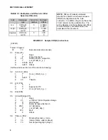
Страница 8: ...ent than the examples in this document EXAMPLE 1 Sample CR10 X Instructions CR10X Table 1 Program 01 10 Execution Interval seconds 01 Pulse P3 1 1 Reps 2 2 Pulse Channel 2 3 22 Switch Closure Output Hz 4 1 Loc WndS_m_s 5 0 7990 Mult 6 0 2811 Offset Set the wind speed to zero if the wind is not blowing 02 If X F P89 1 1 X Loc WndS_m_s 2 1 3 0 2811 F 4 30 Then Do 03 Z F P30 1 0 F 2 0 Exponent of 10 ...
Страница 9: ...1 Reps 2 2 Pulse Channel 2 3 22 Switch Closure Output Hz 4 1 Loc WndS_m_s 5 0 7990 Mult 6 0 2811 Offset Set the wind speed to zero if the wind is not blowing 02 If X F P89 1 1 X Loc WndS_m_s 2 1 3 0 2811 F 4 30 Then Do 03 Z F P30 1 0 F 2 1 Z Loc WndS_m_s 04 End P95 05 AC Half Bridge P5 1 1 Reps 2 5 5000 mV Slow Range 3 5 SE Channel 4 3 Excite all reps w Exchan 3 5 5000 mV Excitation 6 2 Loc WndD_d...
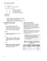
Страница 10: ...turn Materials Authorization RMA number at 801 753 2342 2 Years Replace the wind vane potentiometer and bearings Contact Campbell Scientific for a Return Materials Authorization RMA number at 801 753 2342 7 LONG LEAD LENGTHS When lead lengths greater than 200 feet are required to measure the 034A L use the DC Half Bridge instruction Instruction 4 with a 20 millisecond delay to measure wind directi...
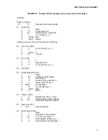
Страница 11: ... 2811 F 4 30 Then Do 03 Z F P30 1 0 F 2 0 Exponent of 10 3 1 Z Loc WndS_m_s 04 End P95 05 Excite Delay SE P4 1 1 Reps 2 5 2500 mV Slow Range 3 5 SE Channel 4 3 Excite all reps w Exchan 3 5 2 Delay units 0 01 sec 6 2500 mV Excitation 7 2 Loc WndD_deg 8 0 288 Mult 9 0 Offset 06 If time is P92 1 0 Minutes Seconds into a 2 30 Interval same units as above 3 10 Set Output Flag High Flag 0 07 Real Time P...
Страница 12: ...20 Ω The maximum value that Rs will reach is 10 kΩ just before it crosses over from the west side of north to the east side of north Vs Vx reaches its maximum value of 0 5 mV mV at 360 degrees Thus the multiplier is 720 degrees Since the datalogger outputs the ratio Vs Vx the multiplier is the same for both the CR10 X and 21X dataloggers even though they use a different excitation voltage See Sect...
Страница 13: ...ce of Air Quality Planning and Standards Research Triangle Park NC 27711 The State Climatologist 1985 Publication of the American Association of State Climatologists Height and Exposure Standards for Sensors on Automated Weather Stations vol 9 No 4 WMO 1983 Guide to Meteorological Instruments and Methods of Observation World Meteorological Organization No 8 5th edition Geneva Switzerland ...
Страница 14: ...This is a blank page ...
Страница 15: ...This is a blank page ...
Страница 16: ... campbellsci com br suporte campbellsci com br Campbell Scientific Canada Corp CSC 11564 149th Street NW Edmonton Alberta T5M 1W7 CANADA www campbellsci ca dataloggers campbellsci ca Campbell Scientific Ltd CSL Campbell Park 80 Hathern Road Shepshed Loughborough LE12 9GX UNITED KINGDOM www campbellsci co uk sales campbellsci co uk Campbell Scientific Ltd France Miniparc du Verger Bat H 1 rue de Te...