
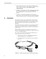


Appendix C. LI200S Pyranometer
C.1 LI200S Pyranometer
LI200S pyranometers have a 100 ohm shunt resistor built into the cable. They
can be directly measured by Campbell Scientific dataloggers. The input range
and multipliers vary from one pyranometer to another. See Appendix C.3,
, for calculating the proper input
range and multiplier.
C.1.1 Wiring
The red lead is connected to the high side (H) of a differential input channel
and the black lead to the corresponding low side (L). On the CR10 a jumper
wire is installed between the low side and analog ground (AG). The clear lead
is connected to ground (G). On the 21X the jumper wire is installed between
the low side and ground (G) and the clear lead is also connected to ground (G).
The measurement is then made with Instruction 2 (see Section 7.4,
Programming
).
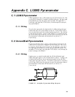
C.2 Unmodified Pyranometers
Pyranometers that do not have variable or fixed shunt resistors built into the
cable can still be measured by Campbell Scientific dataloggers. This is done
by wiring in a 100
Ω
shunt resistor directly onto the datalogger wiring panel.
The input range and multipliers vary from one pyranometer to another. See
Appendix C.3,
, and Appendix C.4,
, for calculating the
proper input range and multiplier.
C.2.1 Wiring
Signal positive is connected into the high side (H) of a differential input
channel and signal negative to the corresponding low side (L). A jumper wire
is installed between the low side (L) and analog ground (AG) on the CR10
wiring panel or ground on the 21X. A 100
Ω
1% resistor (pn 191) is installed
on the wiring panel between the high and low sides the measurement channel.
The measurement is then made with Instruction 2 (see Section 7.4,
Programming
).
FIGURE C-1. Unmodified Pyranometer Wiring Schematic
C-1


