background image

CSAT3B 

Three-Dimensional 

Sonic Anemometer 

Revision: 

5

/19 

Copyright © 2015 – 2019 

Campbell Scientific, Inc. 

Содержание CSAT3B

Страница 1: ...CSAT3B Three Dimensional Sonic Anemometer Revision 5 19 Copyright 2015 2019 Campbell Scientific Inc ...

Страница 2: ...ducts to CSI CSI will return such Products by surface carrier prepaid within the continental United States of America To all other locations CSI will return such Products best way CIP port of entry per Incoterms 2010 This warranty shall not apply to any Products which have been subjected to modification misuse neglect improper service accidents of nature or shipping damage This warranty is in lieu...

Страница 3: ...ping address is CAMPBELL SCIENTIFIC INC RMA _____ 815 West 1800 North Logan Utah 84321 1784 For all returns the customer must fill out a Statement of Product Cleanliness and Decontamination form and comply with the requirements specified in it The form is available from our website at www campbellsci com repair A completed form must be either emailed to repair campbellsci com or faxed to 435 227 9...

Страница 4: ...e beginning work Wear a hardhat and eye protection and take other appropriate safety precautions while working on or around tripods and towers Do not climb tripods or towers at any time and prohibit climbing by other persons Take reasonable precautions to secure tripod and tower sites from trespassers Use only manufacturer recommended parts materials and tools Utility and Electrical You can be kil...

Страница 5: ...ResourceUSB 10 5 2 2 Optional Components 10 5 2 2 1 Sonic Carrying Case 10 5 2 3 Common Accessories 11 5 2 3 1 Power and Communications Cables 11 5 2 3 2 FW05 Thermocouple 13 5 2 3 3 FWC L Cable 13 5 2 3 4 Thermocouple Cover 14 5 2 3 5 Thermocouple Cover Backplate 14 5 2 3 6 FW ENC Thermocouple Enclosure 14 5 2 4 Other Accessories 14 5 2 4 1 Power SDM Splitter 15 5 2 4 2 CPI RS 485 Splitter 15 5 2...

Страница 6: ...Output 51 8 2 4 Operating Mode Recommendations 54 8 3 Synchronization with other sensors 54 8 4 Data Logger Programming using SDM or CPI 55 8 4 1 CRBasic Instructions 55 8 4 1 1 CSAT3B 55 8 4 1 2 CSAT3BMonitor 56 8 4 2 Diagnostic Word 57 8 4 3 SDMTrigger 58 9 Maintenance and Troubleshooting 59 9 1 General Maintenance 59 9 2 Sonic Wicks 59 9 3 Desiccant 60 9 4 Calibration 62 9 4 1 Test for Wind Off...

Страница 7: ...power cable compensation plug 16 5 11 CSAT3B CPI RS 485 splitter 16 5 12 HUB SDM8 for multiple CSAT3B connections with SDM communications 17 5 13 HUB CPI for multiple CSAT3B connections to CPI communications 18 5 14 CAT6 Ethernet cable 18 6 1 Dimensions of CSAT3B 22 7 1 Connecting CSAT3B using Device Configuration Utility 24 7 2 Real time data subscreen while connected to CSAT3B with Device Config...

Страница 8: ... A 1 Magnetic declination for the conterminous United States 2010 A 1 A 2 A declination angle east of true north positive is subtracted from 360 0 degrees to find true north A 2 A 3 A declination angle west of true north negative is subtracted from 0 360 degrees to find true north A 2 A 4 NOAA magnetic declination calculator A 3 A 5 NOAA magnetic calculator results A 4 Tables 4 1 Wiring Diagram fo...

Страница 9: ...B head should be handled by holding the block at the back of the sensor Handling it by the arms or transducers could cause geometric deformation which degrades the measurements o The transducer faces are fragile Care should be taken to avoid scratching or rubbing the surface of the transducer o Grounding the CSAT3B is critical Proper grounding to Earth will ensure maximum electrostatic discharge E...

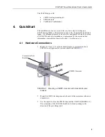
Страница 10: ...s a replacement for the more detailed information on installation found in Section 7 Installation p 22 4 1 Hardware Connections 1 Mount a 3 33 cm 1 31 in outer diameter pipe or crossarm such as a CM20X to a tripod mast or tower as shown in FIGURE 4 1 FIGURE 4 1 Mounting a CM20X crossarm with crossarm to pole bracket 2 Mount the CM250 leveling mount to the end of the crossarm as shown in FIGURE 4 2...

Страница 11: ...round the other end of the wire to the CSAT3B mounting structure or to a grounding rod For more details on grounding see the grounding section of the CR3000 data logger manual If connecting multiple CSAT3Bs together either in a series or a star topology each CSAT3B must be separately grounded to either the mounting structure or a grounding rod FIGURE 4 3 Grounding lug of CSAT3B NOTE CM20X Crossarm...

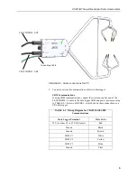
Страница 12: ...f using SDM communications connect a CSAT3BCBL1 L L denotes the cable length in feet cable to the connector on the back of the CSAT3B block labeled Power SDM as shown in FIGURE 4 4 CPI Communications If using CPI communications connect a CSAT3BCBL2 L cable and a CSAT3BCBL3 L RJ to the connectors on the back of the CSAT3B block labelled Power SDM and CPI RS 485 respectively as shown in FIGURE 4 5 F...

Страница 13: ...nd of the CSAT3BCBL1 L cable to the data logger SDM and power ports according to TABLE 4 1 Refer to FIGURE 4 6 which shows these connections to a CR6 data logger TABLE 4 1 Wiring Diagram for CSAT3B with SDM Communications Data Logger Terminal Wire Color 12 V or other 9 5 to 32 VDC source Red Ground Black Ground Brown SDM C1 White SDM C2 Yellow SDM C3 Blue Ground Clear CSAT3BCBL2 L PT CSAT3BCBL3 L ...

Страница 14: ...12 V and ground terminals of a data logger or to a 9 5 to 32 VDC power supply Connect the RJ 45 connector on the end of the CSAT3BCBL3 L RJ to the CPI port on the CPI compatible data logger Use FIGURE 4 7 as a reference FIGURE 4 7 CPI and power connections to a CR6 data logger CSAT3BCBL1 SDM Power cable from CSAT3B Wire to power and SDM ports To 12 VDC power supply CSAT3BCBL3 L RJ CSAT3BCBL2 L PT ...

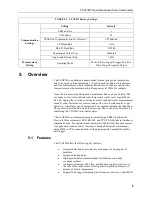
Страница 15: ...utput are triggered by a data logger see Section 8 2 Operating Modes p 48 for more details the CSAT3B Status light will flash red until a data logger is connected to the CSAT3B and its program is running and sending measurement triggers FIGURE 4 8 Lit status light on CSAT3B block 4 3 Factory Settings The CSAT3B is shipped from the factory with the default settings that are shown in TABLE 4 2 These...

Страница 16: ...alar measurements made by other fast response sensors such as fine wire thermocouples or gas analyzers other fluxes can be calculated For example sensible and latent heat fluxes carbon dioxide flux and other trace gas fluxes can all be measured by combining the CSAT3B with other sensors The CSAT3B can communicate measurements using SDM Synchronous Device for Measurements USB RS 485 and CPI CAN Per...

Страница 17: ...2 1 1 CM250 Leveling Mounting Kit The CM250 leveling mounting kit is shipped with the CSAT3B and comes with an adapter FIGURE 5 1 that facilitates mounting a CSAT3B at the end of a 3 33 cm 1 31 in OD crossarm or pipe The kit includes a captive 3 8 in bolt that screws into the bottom of the CSAT3B block and a 3 16 in Allen wrench to tighten the adapter on the pipe FIGURE 5 1 CM250 mount 5 2 1 2 USB...

Страница 18: ...tic Pelican carrying case is available for the CSAT3B It is watertight and highly durable This case is recommended for transporting and storing the CSAT3B It includes a set of foam inserts that hold the CSAT3B in a protected position while providing space for additional components If opting out of the sonic carrying case the CSAT3B will be shipped in a large cardboard box The same set of foam inse...

Страница 19: ...to have pigtail wires for wiring to a power source data logger terminals or a wiring bus The other end has an M16 connector for connecting to the corresponding port at the back of the CSAT3B block The MC option designates an M16 connector on both ends of the cable and is used to daisy chain several CSAT3B instruments together in series Daisy chaining requires ordering the 30293 splitter see Sectio...

Страница 20: ...ired for example CSAT3BCBL3 CPI RS 485 cable for CPI or RS 485 or the 30179 USB data cable For installations with long cable lengths the CSAT3BCBL2 is preferred over the CSAT3BCBL1 for providing power due to the heavier gauge wires that reduce voltage drop over long distances Allowed length is 1 to 550 ft Although the maximum cable length is 550 feet users requiring a cable length of 401 to 550 fe...

Страница 21: ...CSAT3B FIGURE 5 7 FW05 thermocouple Users requiring fine wire thermocouples for atmospheric temperature measurements should consider their data logger choice The CR6 data logger is not optimal for taking fine wire thermocouple measurements For help in choosing the best data logger when fine wire thermocouples are required contact Campbell Scientific 5 2 3 3 FWC L Cable The FWC L is a cable with co...

Страница 22: ...of the FW05 thermocouple it should always be stored in an FW ENC when not in use It is also recommended to order at a minimum a set of four FW05 thermocouples for every CSAT3B as the FW05 will break during normal wear and tear in the field FIGURE 5 8 FW ENC for storing fragile thermocouples 5 2 4 Other Accessories The other accessories available for the CSAT3B are used when combining multiple CSAT...

Страница 23: ...6 connectors The splitter allows connection at the CPI RS 485 port on the back of the CSAT3B block to two CSAT3BCBL3 cables The splitter is IP68 rated It is used for daisy chaining multiple CSAT3Bs in series that use CPI or RS 485 communications A splitter is required for each CSAT3B in the daisy chain except for the terminal one For a daisy chain of CSAT3Bs using SDM communications the CPI RS 485...

Страница 24: ...enough droop to observe this problem If the DC case checks out but the flag is still observed then the system would probably benefit from the addition of a power compensation plug FIGURE 5 10 Both splitters pn 30293 and pn 30294 look similar however they have a different number of pins and are not interchangeable FIGURE 5 11 CSAT3B CPI RS 485 splitter 5 2 4 3 HUB SDM8 The HUB SDM8 shown in FIGURE ...

Страница 25: ...ct the power and SDM connection from a HUB SDM8 to the power and SDM connections on a power source and data logger 5 2 4 5 HUB CPI The 8 channel RJ45 HUB CPI allows up to eight CPI devices to be connected together in parallel In the case of the CSAT3B up to seven CSAT3Bs or CSAT3B daisy chains using CSAT3BCBL3 cables may be connected in parallel to the HUB CPI The remaining port may be used with a...

Страница 26: ...6 Ethernet cable 6 Specifications The CSAT3B measures wind speed and the speed of sound along the three non orthogonal sonic axes The wind speeds are then transformed into the orthogonal wind components ux uy and uz and are referenced to the anemometer head The reported ultrasonic air temperature Ts is the average between the temperatures computed for the three non orthogonal sonic axes The vector...

Страница 27: ...ee Section 4 2 Communications Connections p 4 for a list of all default settings and see Section 8 2 Operating Modes p 48 for more information on modes 6 1 Measurements Operating Temperature Standard 30 to 50 C Wind Accuracy 40 to 50 C wind speed 30 m s 1 azimuth angles between 170 C Offset Error ux 8 cm s 1 max uy 8 cm s 1 max uz 4 cm s 1 max Gain Error Wind Vector 5 of horizontal 2 of reading ma...

Страница 28: ...t max 250 kbps 853 m 2800 ft max 50 kbps Address Range 1 120 Bus Clocks per Sample 300 RS 485 Used for anemometer configuration or computer based data acquisition Baud Rate 9 6 kbps to 115 2 kbps Cable Length 305 m 1000 ft max 115 2 kbps 610 m 2000 ft max 9 6 kbps Bus Clocks per Sample 500 ASCII formatted USB Used for anemometer configuration or computer based data acquisition Connection Speed USB...

Страница 29: ...33 in Support Arm Diameter 1 59 cm 0 63 in Cardboard Box with Foam 73 7 x 45 7 x 25 4 cm 29 x 18 x 10 in Carrying Case with Foam 79 5 x 51 8 x 31 cm 31 3 x 20 4 x 12 2 in Weight Anemometer Head 1 45 kg 3 2 lb Including Cardboard Box Option 5 3 kg 11 7 lb Including Carrying Case Option 13 4 kg 29 5 lb Shipping Both cardboard and carrying cases options are shipped within a second box Cardboard Box O...

Страница 30: ... desired sensor settings orienting mounting and leveling the CSAT3B which is covered in the following sections If the CSAT3B is to be used in a marine environment or in an environment where it is exposed to corrosive chemicals for example the sulfur containing compounds in viticulture attempt to mount the CSAT3B in a way that reduces the exposure of the sonic transducers to saltwater or corrosive ...

Страница 31: ...e port labelled USB on the back of the CSAT3B block Connect the other end of the cable to a USB port on a computer 3 Launch Device Configuration Utility downloaded from www campbellsci com or available on the ResourceUSB 4 From the left side of the main screen select the CSAT3B among the list of sensors Select the appropriate communication port and baud rate refer to the left side of FIGURE 7 1 5 ...

Страница 32: ...hat the appropriate settings are enabled for the communication protocol that will be used An example subscreen is shown in FIGURE 7 2 TABLE 7 1 CSAT3B Settings and Status Values in Device Configuration Utility Subscreen Setting or Status Value Options Description Real Time Data Anemometer Data Shows real time measurements of Ux Uy Uz sonic temperature Ts and the diagnostic word If operating in Mod...

Страница 33: ...ress 1 through 14 31 Unique address for SDM device CPI Address 1 through 120 301 Unique address for CPI device Communication Port Protocol Disable Both CPI Enabled1 RS 485 Enabled Identifies whether the RS 485 CPI port will be disabled enabled for CPI or enabled for RS 485 CPI Baud Rate Auto1 1000 kbps 500 kbps 250 kbps 125 kbps 50 kbps Baud rate for CPI communications in most circumstances this s...

Страница 34: ... the low pass filter Only applicable if in Operating Mode 1 or 3 Sonic Transducer Shadow Correction Disabled Enabled Applies an optional Kaimal correction for wind shadowing of the sonic transducers See Section 8 1 3 Sonic Transducer Shadow Correction p 47 Instrument ID Anemometer Serial Number Serial Number1 The serial number of the CSAT3B User ID String Blank1 A unique identifier in addition to ...

Страница 35: ...tive ux wind In general the anemometer should be pointed into the prevailing wind to minimize interference from support structures such as the tower or tripod Typically the anemometer should be mounted level to the ground as described in Section 7 4 Leveling p 29 7 3 Mounting The CSAT3B is supplied with mounting hardware to attach it to the end of a horizontal pipe with an outer diameter of 3 33 c...

Страница 36: ...T3B to the crossarm by tightening the set screws on the boom adapter with a 3 16 in hex socket head wrench Refer to FIGURE 7 4 4 Attach the CSAT3B to the leveling mount by inserting the bolt on the mount into the threaded hole on the bottom of the CSAT3B block as shown in FIGURE 7 4 5 Lightly tighten the bolt and then proceed to the leveling steps Do not carry the CSAT3B by the arms or the strut b...

Страница 37: ...ation of the CSAT3B or if an application requires a measurement that shows if and when the inclination of the CSAT3B changes over time for example a sagging crossarm or tower tilt an integrated inclinometer in the CSAT3B can give pitch and roll measurements Pitch is the angle between the gravitationally horizontal plane and the CSAT3B x axis A positive pitch angle corresponds to a clock wise rotat...

Страница 38: ...be output using the CRBasic instruction CSAT3BMonitor See Section 8 4 1 2 CSAT3BMonitor p 56 for more information about setting this instruction FIGURE 7 5 CSAT3B shown with coordinate system with arrows representing positive x y and z axes curved arrows indicate positive rotations of pitch and roll angles 7 5 Additional Fast response Sensors 7 5 1 Fine Wire Thermocouple A fine wire thermocouple m...

Страница 39: ...connector of the FW05 into the female connector of the FWC L Finally attach the thermocouple cover to the anemometer block using the thumb screw so that both the FW05 and FWC L connectors are covered See FIGURE 7 6 for positioning and FIGURE 7 7 with the FW05 fully installed FIGURE 7 6 Exploded view of fine wire thermocouple TC with CSAT3B TC Cover Backplate TC Cover FWC L FW05 ...

Страница 40: ...eral mount the analyzer or its intake downwind of the sonic sampling volume 7 6 Wiring On the back of the CSAT3B block there is a copper grounding lug refer to FIGURE 4 3 Use a standard flat head screwdriver to pinch an 8 AWG to 14 AWG wire between the lug and the lug screw Campbell Scientific offers a 10 AWG copper wire that is suitable for grounding sensors Connect the other end of the wire to t...

Страница 41: ...CSAT3B does not include 7 6 m 25 ft lengths of all cable types Only the 5 m 16 ft USB cable for initial configuration of the sensor is included Other cables must be ordered separately TABLE 7 2 Summary of Communications Options for the CSAT3B SDM USB CPI RS 485 Data collection Data loggers CR6 CR800 CR1000X CR3000 Computer Data loggers CR6 CR8001 CR1000X1 CR30001 Computer Cable length Medium Short...

Страница 42: ...that are compatible with the CSAT3B support the same voltage input range as the CSAT3B While the CSAT3B supports voltage of up to 32 VDC many data loggers require lower voltage For example the CR800 and CR3000 require 9 6 to 16 VDC when connecting to the front panel voltage input the CR1000X requires 10 to 18 VDC If a CR3000 has a rechargeable base then a 17 to 28 VDC power supply may be connected...

Страница 43: ...ng cable lengths a higher voltage power supply is recommended as voltage drop over long distances will occur and the CSAT3B requires a minimum of 9 5 VDC FIGURE 7 8 SDM Power connections FIGURE 7 9 Wiring to power and SDM ports on CR6 data logger CSAT3BCBL1 L PT Grounding Cable CSAT3BCBL1 SDM Power cable from CSAT3B Wire to power and SDM ports To 12 VDC power supply ...

Страница 44: ... SDM port of the second CSAT3B Connect another CSAT3BCBL1 to the splitter and down to the next CSAT3B Continue the daisy chain until the last CSAT3B The final CSAT3BCBL1 should have pigtail wire ends to connect to the SDM and 12 V ports of a data logger See FIGURE 7 10 If several CSAT3Bs using SDM communications are being connected in parallel or with a star topology connect a CSAT3BCBL1 cable to ...

Страница 45: ...mensional Sonic Anemometer 37 FIGURE 7 10 SDM daisy chain CSAT3B sensor arms and grounding cables not shown CSAT3BCBL1 L MC CSAT3BCBL1 L MC CSAT3BCBL1 L PT To power supply To power supply 30293 Splitter 30293 Splitter ...

Страница 46: ...e SDM wires will not be used The CSAT3BCSBL1 also has lighter gauge power wires which increases voltage loss over long cable length so it should only be used for shorter cable lengths Next connect a CSAT3BCBL3 to the CPI RS 485 port in the same manner If only one CSAT3B is being measured the opposite end of the power cable should have pigtail wire leads which may be wired to the 12 V and G termina...

Страница 47: ...mensional Sonic Anemometer 39 FIGURE 7 12 Power and CPI cable connections FIGURE 7 13 CPI connection to a CR6 data logger CSAT3BCBL2 L PT CSAT3BCBL3 L RJ Grounding Cable CSAT3BCBL3 L RJ CSAT3BCBL2 L PT To power supply ...

Страница 48: ... pigtail wire ends to connect to the 12 V and G ports of a data logger or to a 12 to 32 VDC power supply The final CSAT3BCBL3 should have an RJ 45 connector that plugs into the CPI port of the data logger Refer to FIGURE 7 14 for the described connections CPI Star Topology If several CSAT3Bs using CPI communications are being connected in parallel or with a star topology connect a CSAT3BCBL2 cable...

Страница 49: ...14 CPI daisy chain CSAT3B sensor arms and grounding cables not shown To power supply To power supply 30293 Splitter 30294 Splitter 30294 Splitter CSAT3BCBL2 L MC CSAT3BCBL3 L MC CSAT3BCBL2 L MC CSAT3BCBL3 L MC CSAT3BCBL2 L PT CSAT3BCBL3 L RJ 30293 Splitter ...

Страница 50: ...CSAT3B Three Dimensional Sonic Anemometer 42 FIGURE 7 15 CPI star topology CSAT3B sensor arms and grounding cables not shown HUB CPI To power supply CAT6 Cable CSAT3BCBL2 L PT CSAT3BCBL3 L RJ ...

Страница 51: ...put Port and Unprompted Output Rate will be grayed out until the operating mode has been set to Mode 2 or Mode 3 To complete installation connect a CSAT3BCBL2 to the Power SDM port by screwing in the M16 connector into the port until tight A CSAT3BCBL1 may also be used for power but the SDM wires will not be used The CSAT3BCSBL1 also has lighter gauge power wires which increases voltage losses ove...

Страница 52: ...h Unprompted Output Port USB Port Unprompted Output Rate 10 20 50 or 100 Hz In Device Configuration Utility the settings for Unprompted Output Port and Unprompted Output Rate will be grayed out until the operating mode has been set to Mode 2 or Mode 3 To complete installation connect a CSAT3BCBL2 to the Power SDM port by screwing in the M16 connector into the port until tight A CSAT3BCBL1 may also...

Страница 53: ...ed ports on the CSAT3B block should always have the caps securely screwed on to avoid water damage to the electronics TABLE 7 3 CSAT3B Cable Wire Assignments CSAT3B Cable Type Signal Description Pigtail Color CSAT3BCBL1 Power 9 5 32 VDC Red Ground Black SDM GND Brown SDM C1 White SDM C2 Yellow SDM C3 Blue Shield Clear CSAT3BCBL2 Power 9 5 32 VDC Red Ground Black CSAT3BCBL3 RxA Brown RxB Brown stri...

Страница 54: ...algorithm Version 5 Version 5 maintains many of the advantages of signal recognition and diagnostic sensitivity that were made possible by Version 3 while also adding the advantages of performance during precipitation events made possible by Version 4 It also resolves Version 4 issues of speed of sound measurement errors in very high wind conditions as reported by Burns et al 2012 see Section 10 1...

Страница 55: ...ead to more shadowing Accordingly an optional wind shadow correction specific to the CSAT3 series transducer diameter and sonic path length has been implemented in the CSAT3B OS versions 1 11 and newer This shadow correction known as the Kaimal correction Kaimal 1979 and Horst et al 2015 is applied according to 𝑈𝑈𝑖𝑖𝑚𝑚𝑚𝑚𝑚𝑚𝑚𝑚𝑚𝑚𝑚𝑚𝑚𝑚𝑚𝑚 𝑈𝑈𝑖𝑖 0 84 0 16 𝑠𝑠𝑠𝑠𝑠𝑠 𝜃𝜃 Where Ui the magnitude of the wind vector...

Страница 56: ...t Mode 1 Self triggered Filtered Data logger prompted output Mode 2 Self triggered No filter Unprompted output to computer Mode 3 Self triggered Filtered Unprompted output to computer The mode is selected using the Device Configuration Utility under the Measurement Settings tab see Section 7 1 Settings p 23 for details on viewing and selecting settings TABLE 8 1 gives a summary of the CSAT3B opera...

Страница 57: ... 5 10 20 25 Data logger 1 to 100 Hz1 2 CSAT3B 100 Hz No CSAT3B 10 20 50 100 Hz 3 CSAT3B 100 Hz Yes 5 10 20 25 CSAT3B 10 20 50 100 Hz 1 The exact rate is determined by the scan interval set in the CRBasic program of the data logger Data logger prompted output using Mode 0 requires use of SDM or CPI communications Data logger prompted output using Mode 1 requires CPI communications SDM not compatibl...

Страница 58: ...CSAT3B and runs them through a low pass high cut filter resulting in a new filtered output at the same 100 Hz rate The degree to which the data are filtered is determined by the user selected filter bandwidth This is selected from the Device Configuration Utility in the Measurement Settings tab The bandwidth is the frequency at which a signal is filtered to 1 1 e of its original power In cases whe...

Страница 59: ...where a data logger provides the measurement trigger Mode 0 the trigger is issued each time the data logger goes through a scan of the program and executes the CSAT3B CRBasic instruction See Section 8 4 1 CRBasic Instructions p 55 for details on the instruction When the trigger is executed it will also prompt the CSAT3B to output the most recent measurement in the buffer This means that the data c...

Страница 60: ... the CSAT3B are 10 20 50 or 100 Hz In unprompted mode the CSAT3B will downsample or decimate the 100 Hz buffer data unfiltered or filtered depending on whether the user has selected Mode 2 or Mode 3 respectively to output at the appropriate rate The unprompted output record is an ASCII string of comma delimited data terminated by a carriage return and contains the following seven data fields 1 ux ...

Страница 61: ...s in the output array should be entered in as the swath The returned value is the computed signature signature signature algorithm Standard signature is initialized with a seed of 0xaaaa Returns signature unsigned short signature unsigned char buf int swath unsigned short seed unsigned char msb lsb unsigned char b int i msb seed 8 lsb seed for i 0 i swath i b lsb 1 msb buf if lsb 0x80 b msb lsb ls...

Страница 62: ...ay is not important when calculating covariances between variables from the CSAT3B since the variables are already synchronized and aligned with one another However when covariances are being calculated between CSAT3B data and data from other fast response sensors the time difference must be accounted for As an example suppose a data logger is making 10 Hz 100 ms measurements of a CSAT3B and an an...

Страница 63: ...82 16 40 80 10 Hz 4 83 20 40 20 Hz 23 43 10 20 25 Hz 83 16 1 Best for flux applications 2 Recommended for spectral analysis 3 Good for flux applications 𝑁𝑁𝑙𝑙𝑙𝑙𝑙𝑙 𝑓𝑓𝑠𝑠𝑠𝑠𝑠𝑠𝑠𝑠 𝐵𝐵𝐵𝐵 4 8 4 Data Logger Programming using SDM or CPI The CSAT3B CRBasic instructions control and retrieve data from the CSAT3B These instructions are available on the CR6 CR800 850 CR1000X and CR3000 data loggers The following s...

Страница 64: ...communication bus For SDM this number may be in the range of 1 to 14 For CPI this number may be in the range 1 to 120 This parameter must be a constant OperatingMode This parameter controls whether the CSAT3B will operate in Mode 0 or Mode 1 see Section 8 2 Operating Modes p 48 for more details This parameter must be a constant and may have one of the following values 0 5 10 20 or 25 The meaning o...

Страница 65: ...ange 1 to 14 For CPI this number may be in the range 1 to 120 This parameter must be a constant 8 4 2 Diagnostic Word The fifth output from the CSAT3B is the diagnostic word The diagnostic word describes the status of the anemometer and is useful in filtering data For example when the anemometer is locking in on the ultrasonic signals after receiving the acquire signals command the NaN it sends to...

Страница 66: ...nvestigate whether cable lengths are excessive 6 0x0040 64 Trigger Error A measurement trigger has not been received for at least 1 sec or the time interval between triggers is varying by greater than 5 Check wiring to the data logger and check the data logger program for the expected trigger rate 7 0x0080 128 Internal Humidity Warning The relative humidity inside the CSAT3B block is greater than ...

Страница 67: ...he wicking properties of the sonic wicks may not be adequate In these circumstances the CSAT3B may report diagnostic error conditions or erroneous data until the water droplets evaporate or are manually removed Droplets can be removed by dabbing a cotton swab or tissue on the face of the transducer If site conditions are such that the wicks are unnecessary gently remove the wicks from the transduc...

Страница 68: ...ature decreases the capacity of air to hold water also decreases and the relative humidity will increase even if no additional water has been introduced into the closed system As the relative humidity approaches 100 condensation will begin to form on the internal surfaces The CSAT3B has a cavity to hold a replaceable desiccant canister that removes water from the air see FIGURE 9 2 Water molecules...

Страница 69: ... unused one The new canister should appear blue in color A pink hued canister indicates that moisture has been absorbed and the canister should be discarded and replaced with a new one When replacing the brass screw cap ensure the cap is tightened until the head of the screw is flush with the housing and the o ring cannot be seen Replacement desiccant canisters are shipped in a vacuum sealed bag T...

Страница 70: ...chen waste bin liner The following steps should be taken to test the CSAT3B for wind offset 1 Mount the head using the horizontal mount boom as described in Section 4 1 Hardware Connections p 2 or hang the head from the block that supports the CSAT3B upper and lower arms Do not lay the CAST3B head on its side or balance it on the transducers as this will affect its measurements 2 Cover the CSAT3B ...

Страница 71: ... Three Dimensional Sonic Anemometer 63 FIGURE 9 3 CSAT3B real time data with 1 sec update and ux and uy wind component graphed FIGURE 9 4 CSAT3B real time data with 1 sec update and uz wind component graphed ...

Страница 72: ...thing that might obstruct the sonic signal Check for signs that the geometry of the arms has changed in any way possibly from an impact from another object 2 Check all wiring connections between the CSAT3B and data logger 3 Check to see if the diagnostic flags are still high 4 If diagnostic flags persist remove the CSAT3B from the site and perform a zero wind offset as described in Section 9 4 1 T...

Страница 73: ...urn the CSAT3B either for calibration or repair please follow the detailed instructions provided in the Assistance section at the beginning of this manual which gives instructions for generating an RMA number If additional help is needed please contact Campbell Scientific When preparing the CSAT3B for shipment be sure to package it in the same foam that it was sent in If the foam cannot be found n...

Страница 74: ...nsducer Shadowing Boundary Layer Meteorol 155 371 395 DOI 10 1007 s10546 015 0010 3 Schotanus P Nieuwstadt F T M and de Bruin H A R 1983 Temperature Measurement with a Sonic Anemometer and its Application to Heat and Moisture Fluxes Boundary Layer Meteorol 26 81 93 Burns S P Horst T W Jacobsen L Blanken P D and Monson R K 2012 Using sonic anemometer temperature to measure sensible heat flux in str...

Страница 75: ... the number of degrees between True North and Magnetic North Magnetic declination for a specific site can be obtained from a USGS map local airport or through a NOAA web calculator Appendix A 2 Online Magnetic Declination Calculator p A 3 A general map in FIGURE A 1 taken from www ngdc noaa gov geomag img DeclinationMap_US png shows magnetic declination for the conterminous United States in 2010 F...

Страница 76: ...acted from a positive number the resulting arithmetic operation is addition For example the declination for Longmont CO 10 June 2006 is 9 67 degrees the angle is East of True North so it is reported as positive thus True North is 360 degrees 9 67 degrees or 350 33 degrees as read on a compass Likewise the declination for Mc Henry IL 10 June 2006 is 2 68 degrees and True North is 0 degrees 2 68 deg...

Страница 77: ...ished by NOAA s Geophysical Data Center is available at the following URL www ngdc noaa gov geomag web declination After the web page loads enter the zip code country and city or latitude and longitude of the site then click on Calculate to get the declination for that site FIGURE A 4 FIGURE A 4 NOAA magnetic declination calculator ...

Страница 78: ...sults The declination for Salt Lake City UT is 11 7 degrees 4 November 2014 As shown in FIGURE A 5 the declination for Utah is positive east of north so true north for this site is 360 11 7 or 348 3 degrees The annual change is 7 8 minutes year or 7 8 minutes west per year ...

Страница 79: ...ucer axis d distance between the transducers c speed of sound The wind speed ua along any axis can be found by inverting the above relationships then subtracting Eq B 2 from B 1 and solving for ua u d t t a o b 2 1 1 B 3 The wind speed is measured on all three non orthogonal axis to give ua ub and uc where the subscripts a b and c refer to the non orthogonal sonic axis The non orthogonal wind spee...

Страница 80: ...specific heat of moist air at constant pressure to that at constant volume P pressure ρ air density Rd gas constant for dry air Tv virtual temperature T air temperature q specific humidity defined as the ratio of the mass of water vapor to the total mass of air as in Kaimal and Gaynor 1991 and Wallace and Hobbs 1977 Note that γ is a function of specific humidity It would be convenient if the effec...

Страница 81: ... and Rd 287 04 JK 1 kg 1 T c R s d d 2 273 15 γ B 9 B 2 References Kaimal J C and Businger J A 1963 A Continuous Wave Sonic Anemometer Thermometer J Applied Meteorol 2 156 164 Kaimal J C and Gaynor J E 1991 Another Look at Sonic Thermometry Boundary Layer Meteorol 56 401 410 Fleagle R G and Businger J A 1980 An Introduction to Atmospheric Physics Academic Press Inc New York Liu H Peters G and Foke...

Страница 82: ...als 4 SonTemp Alias CSATVals 5 Diag Alias CSATMonitorVals 1 BoardTemp Alias CSATMonitorVals 2 BoardHumidity Alias CSATMonitorVals 3 InclinePitch Alias CSATMonitorVals 4 InclineRoll Define Data Tables DataTable SonicData 1 1 Sample 5 CSATVals 1 IEEE4 EndTable DataTable MonitorData 1 1 DataInterval 0 5 Sec 10 Sample 4 CSATMonitorVals 1 IEEE4 EndTable Main Program BeginProg Scan 50 msec 500 0 20 Hz S...

Страница 83: ...ias CSATMonitorVals 1 BoardTemp Alias CSATMonitorVals 2 BoardHumidity Alias CSATMonitorVals 3 InclinePitch Alias CSATMonitorVals 4 InclineRoll Define Data Tables DataTable SonicData 1 1 Sample 5 CSATVals 1 IEEE4 EndTable DataTable MonitorData 1 1 DataInterval 0 5 Sec 10 Sample 4 CSATMonitorVals 1 IEEE4 EndTable Main Program BeginProg Scan 50 msec 500 0 20 Hz Scan CSAT3B Destination Bus Address Ope...

Страница 84: ...VAL 5 Period of 5 sec for monitor data Const STATS_INTERVAL 1 Period of 30 min for online statistics Const CPI_RATE 125 Set CPI Rate to 250 ksps Const N_STATS 1 Increment size in the totalization functions Const CSAT_AZIMUTH 0 Unique value Compass azimuth of the x axis For the figure below CSAT3B_AZIMUTH 90 Compass coordinate system Right handed coordinate system N y W x X x E CSAT3B Block CSAT3B ...

Страница 85: ...r Flag Alias diag_bits 9 Flag_TrigErr Trigger Error Flag Wind directions and speed Public wind_out 8 Alias wind_out 1 wind_spd in compass coord system same as CSAT3B Alias wind_out 2 result_wind_speed in compass coord system same as CSAT3B Alias wind_out 3 wind_dir_compass Alias wind_out 4 standard_wind_dir in compass coord system same as CSAT3B Alias wind_out 5 wind_speed Alias wind_out 6 result_...

Страница 86: ...talize 1 N_STATS IEEE4 NOT Flag_LowAmp OR NOT disable_stats 2 FieldNames Flag_LowAmp_Tot Totalize 1 N_STATS IEEE4 NOT Flag_HighAmp OR NOT disable_stats 2 FieldNames Flag_HighAmp_Tot Totalize 1 N_STATS IEEE4 NOT Flag_Tracking OR NOT disable_stats 2 FieldNames Flag_Tracking_Tot Totalize 1 N_STATS IEEE4 NOT Flag_HighDeltaC OR NOT disable_stats 2 FieldNames Flag_HighDeltaC_Tot Totalize 1 N_STATS IEEE4...

Страница 87: ...0080 diag_bits 9 diag_integer AND h00000100 Turn on this intermediate processing disable flag when any warning flag is set or the data returned is NaN disable_stats 1 diag_integer AND hffffffff OR diag NaN Turn on this intermediate processing disable flag only when CSAT3B diagnostic warning flags are set disable_stats 2 diag_integer AND hffffffff AND NOT diag NaN Compute the online wind vector sta...

Страница 88: ...0033 0 1 56 45 15 20 Email info campbellsci fr Website www campbellsci fr Germany Location Bremen Germany Phone 49 0 421 460974 0 Email info campbellsci de Website www campbellsci de South Africa Location Stellenbosch South Africa Phone 27 21 8809960 Email sales campbellsci co za Website www campbellsci co za Southeast Asia Location Bangkok Thailand Phone 66 2 719 3399 Email thitipongc campbellsci...

Отзывы: