


CS800-L CLIMATRONICS WIND SPEED AND DIRECTION SENSOR
3
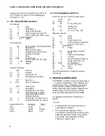
3. INSTALLATION
3.1 SITING
As a rule of thumb, wind sensors should be
located away from obstructions (e.g., trees or
buildings) by a horizontal distance of at least ten
times the height of the obstruction. If it is
necessary to mount the sensors on the roof of a
building, the height of the sensors above the
roof should be at least 1.5 times the height of
the building.
3.2 SENSOR MOUNTING
Tools Required:
•
5/64” (for 019ALU crossarm) and 1/16”
allen wrenches
•
compass and declination angle for site
•
small screwdriver provided with datalogger
•
UV resistant cable ties
•
small pair of diagonal-cutting pliers
•
6 - 10” torpedo level
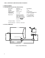
Attach the vane and cupset to the crossarm
shafts as shown in Figure 1. Place the cupset
on the shaft directly above the circular
connector and tighten the two set screws.
Place the vane on the opposite shaft and align
the flats on the vane hub and shaft as indicated.
A small coin held against the flats will maintain
the alignment of the flats while the two set
screws are tightened.
The CS800-L crossarm mounts to the top of the
UT930 tower as shown in Figure 1. Orient the
019ALU crossarm so that the end with the 3/4”
NU-RAIL connector points North. Position the
top of the 3/4” mounting post (provided with the
sensor) 5” above the NU-RAIL and tighten the
two set screws. Mount the sensor crossarm to
the mounting post. Orient the sensor crossarm
so that the vane end points East and tighten the
set screws. Level the sensor crossarm by
adjusting the NU-RAIL connector attached to
the 019ALU crossarm. Refer to the UT930
Weather Station Installation Manual for a
discussion on declination angle and sensor
alignment to True North.
Attach the sensor cable to the crossarm
connector. Make sure both connectors are
properly keyed and tighten the knurled ring
finger-tight. Route the sensor cable along the
underside of the crossarm to the tower mast
and down a tower leg to the instrument
enclosure. Secure the cable to the crossarm
and mast using cable ties.
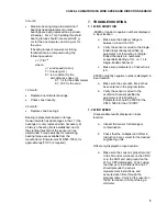
4. SENSOR WIRING
Wire the CS800-L to the datalogger as shown in
Figure 3.
Photochopper
circuit for
wind speed
A
B
C
D
E
F
1 M
N/C
6-Pin
Connector
Cable
Datalogger
black/red
(wind speed reference)
white
(5-7 VDC)
black/green
(azimuth reference)
red
(wind speed signal)
black/white
(azimuth excitation)
green
(azimuth signal)
clear
(shield)
G
5V**
AG*
P1
E2
SE4
G
CS800-L
2 K
Figure 3. CS800-L Wiring
*
Ground on the 21X and CR7
** CAO port set to 5V on the 21X and CR7
The excitation, pulse and analog input channels
listed above correlate with the measurement
instructions shown in Section 5, and those that
are used with the WeatherPro Software. The
input channels and input locations are intended
as examples only.
5. DATALOGGER PROGRAMMING
The output from the anemometer is a high
frequency pulse that is measured with
Instruction 3. Use a configuration code of 20 for
parameter 3, which gives a result in frequency.
The multiplier and offset converts the frequency
to the desired wind speed units (see example
below).
Wind direction is measured with Instruction 4.
Use an excitation voltage of 2500 with the
CR10, or 5000 mV with the 21X or CR7
dataloggers. The potentiometer has an
electrical range of 355°, with a 5° dead band
between 355 - 360°. The multiplier to convert
mV to degrees is 355 degrees / excitation
Содержание CS800-L
Страница 4: ...This is a blank page ...
Страница 10: ...CS800 L CLIMATRONICS WIND SPEED AND DIRECTION SENSOR 6 This is a blank page ...
Страница 11: ...This is a blank page ...


