


4.3 Mounting
A pole mounting kit is supplied with the CS140. This kit includes a mounting plate, two V-bolts
and suitable bolts for clamping the pole between the plate and brackets.
To mount the CS140 onto a pole:
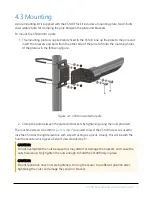
1. The mounting plate is supplied ready fixed to the CS140. Line up the plate to the pole and
insert the brackets and bolts from the other side of the pole to fit into the matching holes
of the plate as in the following figure.
Figure 4-1. CS140 mounted on pole
2. Clamp the pole between the plate and brackets by tightening using the nuts provided.
The machine screws A and B in
(p. 7) are used to level the CS140. Screw A is used to
lock the CS140 at the right elevation with screw B acting as a pivot. Usually, this will be with the
hood horizontal which gives a field of view elevated by 6°.
CAUTION:
Do not overtighten the nuts because this may distort or damage the brackets, and cause the
nuts to seize up. Only tighten the nuts enough to hold the CS140 firmly in place.
CAUTION:
Do not reposition once nuts are tightened. Forcing the sensor to a different position after
tightening the nuts can damage the sensor or bracket.
CS140 Background Luminance Sensor
7


