


Section 7. Installation
Table 21.
Binary Conditions of TRUE and FALSE
Condition
CRBasic Instruction(s)
Used
Memory Location of Binary
Result
Time
TimeIntoInterval()
Variable, System
IfTime()
Variable, System
TimeIsBetween()
Variable, System
Control Port Trigger
WaitDigTrig()
System
Communications
VoiceBeg()
System
ComPortIsActive()
Variable
PPPClose()
Variable
Measurement Event
DataEvent()
System
Using TRUE or FALSE conditions with logic operators such as AND and OR,
logical expressions can be encoded to perform one of the following three general
logic functions. Doing so facilitates conditional processing and control
applications:
1. Evaluate an expression, take one path or action if the expression is true (= –1),
and / or another path or action if the expression is false (= 0).
2. Evaluate multiple expressions linked with
AND
or
OR
.
3. Evaluate multiple
AND
or
OR
links.
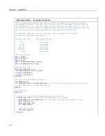
The following commands and logical operators are used to construct logical
expressions. CRBasic example
Logical Expression Examples
(p. 165)
demonstrate
some logical expressions.
•
IF
•
AND
•
OR
•
NOT
•
XOR
•
IMP
•
IIF
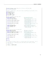
Table 22.
Logical Expression Examples
If X >= 5 then Y = 0
Sets the variable Y to 0 if the expression "X >= 5" is true, i.e. if X is greater than or equal to 5. The CR1000 evaluates the
expression (X >= 5) and registers in system memory a
-1
if the expression is true, or a
0
if the expression is false.
If X >= 5 OR Z = 2 then Y = 0
Sets Y = 0 if either X >= 5 or Z = 2 is true.
If X >= 5 AND Z = 2 then Y = 0
Sets Y = 0 only if both X >= 5 and Z = 2 are true.
If 6 then Y = 0.
If 6
is true since
6
(a non-zero number) is returned, so Y is set to
0
every time the statement is executed.
If 0 then Y = 0.
If 0
is false since
0
is returned, so Y will never be set to
0
by this statement.
Z = (X > Y).
Z equals
-1
if X > Y, or Z will equal
0
if X <= Y.
165
Содержание CR1000
Страница 2: ......
Страница 4: ......
Страница 6: ......
Страница 32: ......
Страница 36: ......
Страница 38: ......
Страница 40: ......
Страница 60: ...Section 4 System Quickstart Figure 16 PC200W View Line Graph 60 ...
Страница 96: ......
Страница 98: ...98 ...
Страница 302: ......
Страница 350: ...Section 8 Operation Figure 91 Pulse Sensor Output Signal Types Figure 92 Switch Closure Pulse Sensor 350 ...
Страница 453: ...Section 8 Operation Figure 115 Using the Keyboard Display 453 ...
Страница 454: ...Section 8 Operation 8 8 1 Data Display Figure 116 Displaying Data with the Keyboard Display 454 ...
Страница 456: ...Section 8 Operation Figure 118 Real Time Custom 456 ...
Страница 457: ...Section 8 Operation 8 8 1 3 Final Memory Tables Figure 119 Final Memory Tables 457 ...
Страница 458: ...Section 8 Operation 8 8 2 Run Stop Program Figure 120 Run Stop Program 458 ...
Страница 460: ...Section 8 Operation Figure 122 File Edit 460 ...
Страница 461: ...Section 8 Operation 8 8 4 PCCard Memory Card Display Figure 123 PCCard CF Card Display 461 ...
Страница 478: ......
Страница 506: ......
Страница 536: ......
Страница 636: ......
Страница 642: ......
Страница 644: ......
Страница 676: ......
Страница 677: ......