


10.
Reconnect to the datalogger using Device
Configuration Utility. On the Cellular tab, enter the
APN provided by your cellular provider. For Telstra, this
will most commonly be "
telstra.internet
" (without
quotes).
11.
At this stage, we recommend to archive a copy of the
logger settings on your computer. To save a copy of
these settings for future use, click
Summary
then
Save
and select a folder on your PC.
12.
Click
Apply
to save the changes.
13.
Once changes have been applied, disconnect from
the data logger and close Device Configuration Utility
5.3
Set up LoggerNet
1.
Open Loggernet.
2.
Go to
Main
>
Setup
to open the Setup screen.
3.
Set Standard view by selecting
View
>
Standard
4.
Select
Add Root
>
IPPort
.
5.
Select
PakBusPort
then
pbRouter for PakBus
data loggers such as the CR1000X.
6.
Add the relevant data logger to the
pbRouter
(in our
example, it is a CR1000X).
7.
In the
Entire Network
window on the left, select the
IPPort
in the Network Map. The DNS and Port
information (from the Konect Pakbus Router information
in Step 4.2) is used in this step. Enter them into the
Internet IP Address
field in the format DNS:Port with a
colon separating DNS and Port. For example,
axanar.konectgds.com:pppp where pppp is the port
number.
8.
In the
PakBusPort
, please make sure that the box
corresponding to
PakBus Port Always Open
is unticked.
In the "TCP Password" field, enter the TCP password.
9.
For PakBus data loggers, select the pbRouter in the
Network Map and set the
PakBus Address
to
4070
.
10.
For PakBus data loggers, select the data logger in the
Network Map and set the
PakBus Address
to match that
of the data logger (default address in the data logger is 1).
Click
Apply
to save the changes.
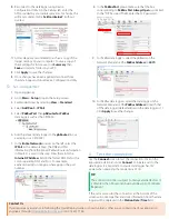
6.
Test the connection
Use the
Connect
screen to test the connection. Click on the
appropriate station and click
Connect
to initiate a call to the
data logger. It is important to ensure data logger has 12V
power when powering the modem via CS I/O.
If the call is successful, the connectors at the bottom of the
screen will come together and clock information from the data
logger will be displayed in the
Station Date/Time
field.
TIP:
The connection time is subject to many external factors. It
is often less than 30 seconds but could be up to 15 minutes.
Be patient.
Contact Us
If you require any assistance in following this Quick Deploy Guide or you run into any other issues, contact one of our application
engineers through


