Campbell Bowen Ratio Instrumentation Скачать руководство пользователя страница 1

INSTRUCTION MANUAL

Bowen Ratio Instrumentation

Revision: 9/05

C o p y r i g h t   ( c )   1 9 8 7 - 2 0 0 5

C a m p b e l l   S c i e n t i f i c ,   I n c .

Содержание Bowen Ratio Instrumentation

Страница 1: ...INSTRUCTION MANUAL Bowen Ratio Instrumentation Revision 9 05 C o p y r i g h t c 1 9 8 7 2 0 0 5 C a m p b e l l S c i e n t i f i c I n c ...

Страница 2: ... other warranties expressed or implied including warranties of merchantability or fitness for a particular purpose CAMPBELL SCIENTIFIC INC is not liable for special indirect incidental or consequential damages Products may not be returned without prior authorization The following contact information is for US and International customers residing in countries served by Campbell Scientific Inc direc...

Страница 3: ...Sensor Height and Separation 2 1 2 2 Soil Thermocouples and Heat Flux Plates 2 2 2 3 Wiring 2 4 2 4 Battery Connections 2 7 2 5 System Startup 2 7 2 6 Routine Maintenance 2 7 2 7 Cleaning the DEW 10 2 8 3 Sample CR23X Program 3 1 4 Calculating Fluxes Using SPLIT 4 1 4 1 Data Handling 4 1 4 2 Calculating Fluxes 4 1 Appendices A References A 1 B 023 Bowen Ratio Pre July 1993 B 1 Tables 1 2 1 Compone...

Страница 4: ...uples and Heat Flux Plates 2 3 2 2 2 TCAV Spatial Averaging Thermocouple Probe 2 4 2 3 A block diagram for the connections between the datalogger the BR relay driver and components and the external battery 2 6 2 4 1 Terminal Strip Adapters for Connections to Battery 2 7 2 7 1 DEW 10 Circuit Board 2 9 B 1 023 Bowen Ratio Vapor Measurement System with Three Flowmeters B 1 ...

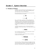
Страница 5: ...sually causes negligible error The eddy diffusivities are functions of height The vapor and temperature gradients reflect temporal and spatial averages Applying the Universal Gas Law to Eq 1 and using the latent heat of vaporization λ the latent heat flux density λ can be written in terms of vapor pressure e L k P e z e v λρε 3 Here P is atmospheric pressure and ε is the ratio of the molecular wei...

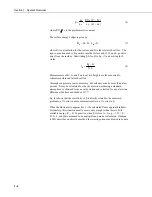
Страница 6: ...e is also necessary but seldom varies by more than a few percent It may be calculated for the site elevation assuming a standard atmosphere or obtained from a nearby station and corrected for any elevation difference Wallace and Hobbes 1977 Eq 6 shows that the sensitivity of β is directly related to the measured gradients a 1 error in a measurement results in a 1 error in β When the Bowen ratio ap...

Страница 7: ...samples from two heights are routed to the cooled mirror after passing through mixing volumes Figure 1 2 1 The problems associated with wick wetting and water supply in psychrometers are avoided and systematic sensor errors are eliminated Air is drawn from both heights continuously through inverted 25 mm filter holders fitted with Teflon filters with a 1 µm pore size The filter prevents dust conta...

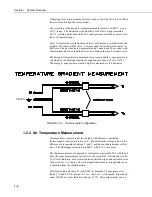
Страница 8: ...scribed by Lowe 1976 The average vapor pressure at each height is calculated every 20 minutes CR23X FIGURE 1 2 2 Thermocouple Configuration 1 2 2 Air Temperature Measurement Air temperature is measured at two heights with chromel constantan thermocouples wired as in Figure 1 2 2 The differential voltage is due to the difference in temperature between T1 and T2 and has no inherent sensor offset err...

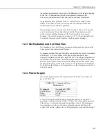
Страница 9: ...e soil heat flux heat flux plates are buried in the soil at a fixed depth of between 5 to 10 cm to reduce errors due to vapor transport of heat Typically the plates are buried at a depth of 8 cm The average temperature of the soil layer above the plate is measured using 4 parallel thermocouples The heat flux at the surface is then calculated by adding the heat flux measured by the plate to the ene...

Страница 10: ...Section 1 System Overview 1 6 This is a blank page ...

Страница 11: ...ng the height at which to mount the support arms for the temperature and air intakes The differences in temperature and moisture increase with height so the resolution on the measurements of the temperature and vapor gradient will improve the farther apart the arms are The upper mounting arm must be low enough that it is not sampling air that is coming from a different environment upwind The air t...

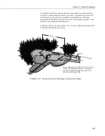
Страница 12: ...f the two heat flux plates thermocouples should be chosen to be representative of the area under study If the ground cover is extremely varied it may be necessary to have additional sensors to provide a valid average Use a shovel to cut a vertical slice in the soil and remove the soil to one side of the cut Try to keep the soil that is removed intact so that it can be replaced with as little disru...

Страница 13: ...ame level as the sensor for as long as possible Once the sensors are installed backfill the hole Install the CS616 as shown in Figure 2 2 1 See the CS616 manual Section 5 for detailed installation instructions 2 cm 6 cm 8 cm Ground Surface Up to 1 m 2 5 cm FIGURE 2 2 1 Placement of Thermocouples and Heat Flux Plates Partial emplacement of HFT3 and TCAV sensors is shown for illustration purposes Al...

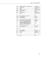
Страница 14: ...losest to the reference temperature thermistor The input terminal strip cover for the CR23X must be installed once all connections have been made and verified Section 13 4 of CR23X manual TABLE 2 3 1 CR23X Sensor Connections for Example Program CHANNEL SENSOR COLOR 1H Q7 1 RED 1L Q7 1 BLACK SHIELD CLEAR 2H HYGROMETER PRT GREEN 2L HYGROMETER PRT WHITE HYGROMETER PRT BLACK 3H TCAV PURPLE 3L TCAV RED...

Страница 15: ... BLACK CLEA R EX1 HYGROMETER EXCITATION RED EX2 WIND SENTRY BLACK GND HYGROMETER CLEAR C1 PULSE FOR LOWER AIR INTAKE GREEN C2 PULSE FOR UPPER AIR INTAKE WHITE C3 PULSE TO TURN ON POWER TO MIRROR AND PUMP FLAG 6 BLACK C4 PULSE TO TURN OFF POWER TO MIRROR AND PUMP FLAG 7 RED C7 CS615 TURN UNIT ON ORANGE G GROUND WIRE CLEAR PULS E 1 WIND SENTRY BLACK WIND SENTRY WHITE CLEAR 2 CS615 GREEN CS615 BLACK ...

Страница 16: ...Section 2 Station Installation 2 6 C R 2 3 X FIGURE 2 3 A Block Diagram for the Connections between the Datalogger the BR Relay Driver and Components and the External Battery ...

Страница 17: ... panel 2 5 System Startup To bring the Bowen ratio system on line turn on the datalogger set the datalogger time download the program and set flag 6 high to activate the hygrometer and pump 2 6 Routine Maintenance Change air intake filters 1 2 weeks Clean mirror and adjust bias 1 2 weeks Clean thermocouples as needed Clean Radiometer domes as needed Filters are Teflon 25 mm diameter with a 1 µm po...

Страница 18: ...moelectric cooler by sliding switch S1 toward the nearest end of the card out of the operate position OP and into the balance position BAL 3 Remove the DEW 10 connector from the circuit board Figure 2 7 1 Pull firmly on the DEW 10 until it slides out of the mirror block 4 Locate the mirror it is circular in shape and only the edge can be seen when looking straight into the mirror cavity The mirror...

Страница 19: ...ce ended Cleaning the mirror with a cotton swab does not result in a surface condition like the one reached after evaporation of a dew layer Therefore a more appropriate bias adjustment is reached with a mirror surface on which a dew layer has been formed and then evaporated By adding two steps to the above procedure a more appropriate bias adjustment can be made and the period between required mi...

Страница 20: ...Section 2 Station Installation 2 10 This is a blank page ...

Страница 21: ...a different installation is to be used the program will have to be altered Note that even if this exact installation is used the correct calibration multiplier and offset must be entered for the net radiometer and soil heat flux plates Table 3 1 is a flow chart of the example program and Table 3 2 lists the output generated by the program Power to the pump and cooled mirror is switched on and off ...

Страница 22: ...re Yes Flag 5 Set No Yes 20 Minute Interval No Set Flag 0 Output Yes Flag 4 Set No Set Flag 0 Output Set Flag 5 process Day Hour Minute smpl Panel Temperature smpl Lower Temperature avg Temperature Gradient avg Yes Flag 2 Set No Set Flag 9 Disable Intermediate Processing Yes Flag 1 Set No Set Flag 9 Disable Intermediate Processing process Upper Dew Point avg Upper Vapor Pressure avg Reset Flag 9 Y...

Страница 23: ...adiation Call Subroutine 4 wind speed correction on negative radiation Measure 2 Soil Heat Flux Plates Measure Soil Temperature Layer Average Scale Heat Flux Measurements Wind Speed Wind Direction Yes Ten Minutes Into Interval No Measure CS615 Yes Last 10 Minutes of a 20 Minute Interval No Compute Average Soil Temperature Yes 20 Minute Interval No Calculate 10 Minute Soil Temp avg Calculate Change...

Страница 24: ...Turn off Pump and Mirror Reset Flag 7 Yes Battery Volts 11 5 No Yes Flag 3 Reset No Yes Flag 3 Reset No Yes Battery Voltage 12 No Set Port 4 High Delay 0 01 Seconds Set Port 4 Low Set Flag 3 output process Day Hour Minute Battery Voltage smpl Set Port 3 High Delay 0 01 Seconds Set Port 3 Low Reset Flag 3 output process Day Hour Minute Battery Voltage smpl Subroutine 3 Positive net radiation Apply ...

Страница 25: ...lux 2 07 Avg soil temp Last 10 min 08 Change from previous soil temp 09 Avg wind speed 10 Avg wind direction 11 Standard deviation of wind direction 12 CS615 period 13 Volumetric soil water content 14 Volumeric soil water content corrected for temperature 15 Avg battery voltage 01 302 Beginning of site maintenance 02 Day 03 hhmm 01 303 End of site maintenance 02 Day 03 hhmm 01 317 Pump and cooled ...

Страница 26: ...Section 3 Sample CR23X Program 3 6 This is a blank page ...

Страница 27: ...vice or when it shut itself down because of low battery voltage Next combine the air temperature and vapor pressure gradients with net radiation soil heat flux soil temperature wind speed and wind direction using the SPLIT parameter file RAWBOW PAR This parameter file assumes that the data files from the datalogger were saved on disk under the name BOWEN DAT It creates a file with the raw data nec...

Страница 28: ... of water This calculation requires site specific inputs for bulk density mass basis soil water content or volume basis soil water content and the specific heat of the dry soil Bulk density and mass basis soil water content can be found by sampling Klute 1986 The volumetric soil water content is measured by the CS615 soil water content reflectometer The value used for the heat capacity of dry soil...

Страница 29: ...s BD 1200 kg m3 Soil bulk density must be measured for site W vol H2O bulk vol soil Soil water content volume basis measured by the CS615 F W m2 Soil heat flux measured at 8 cm S W m2 Heat stored calculated from soil heat capacity and measured change in temperature G W m2 Soil heat flux at surface F S RN W m2 Net radiation measured BR Bowen ratio LE W m2 Latent heat flux H W m2 Sensible heat Flux ...

Страница 30: ...Section 4 Calculating Fluxes Using SPLIT 4 4 This is a blank page ...

Страница 31: ...R 1960 Photosynthesis under field conditions II An aerodynamic method for determining the turbulent carbon dioxide exchange between the atmosphere and a corn field Agron J 52 697 703 Lowe P R 1976 An approximating polynomial for computation of saturation vapor pressure J Appl Meteor 16 100 103 Ohmura A 1982 Objective criteria for rejecting data for bowen ratio flux calculations J Appl Meteor 21 59...

Страница 32: ...Appendix A References A 2 Wallace J M and P V Hobbes 1977 Atmospheric Science An Introductory Survey Academic Press 350 pp ...

Страница 33: ...B 1 Appendix B 023 Bowen Ratio Pre July 1993 FIGURE B 1 023 Bowen Ratio Vapor Measurement System with Three Flowmeters ...

Страница 34: ...This is a blank page ...

Страница 35: ...This is a blank page ...

Страница 36: ... campbellsci com br suporte campbellsci com br Campbell Scientific Canada Corp CSC 11564 149th Street NW Edmonton Alberta T5M 1W7 CANADA www campbellsci ca dataloggers campbellsci ca Campbell Scientific Ltd CSL Campbell Park 80 Hathern Road Shepshed Loughborough LE12 9GX UNITED KINGDOM www campbellsci co uk sales campbellsci co uk Campbell Scientific Ltd France Miniparc du Verger Bat H 1 rue de Te...

Отзывы: