background image

2-1

SECTION 2.  TEMPERATURE MEASUREMENT

2.1  GENERAL

The vibrating wire probe includes a thermistor
which is used to measure the temperature of
the probe.  Probe temperature is used to correct
errors in the vibrating wire measurement
caused by changes in the temperature of the
probe.  The temperature correction is most
important when the temperature of the medium
the probe is measuring is changing (e.g. water
temperature in a river or shallow lake).  When
concerned with the absolute reading, it is also
important to make the temperature correction if
the medium temperature differs from the
calibration temperature.  In a deep well where
the water temperature does not change, the
error due to temperature can be removed by
allowing the sensor to come to thermal
equilibrium and adjusting the sensor reading to
read the correct depth by means of an offset.

2.2  ACCURACY AND RESOLUTION

The accuracy of the temperature measurement
is a function of the following factors listed in
decreasing importance:  

1)

 the thermistor's

interchangeability,  

2)

 the resistance of the wire,

3)

 the linearization error,  

4)

 the precision of the

bridge resistors,  

5)

 the accuracy of the

datalogger's voltage measurement, and  

6)

 the

temperature coefficient of the bridge resistors.
The interchangeability of the thermistor is

±

0.5

o

C although a thermistor with 

±

0.2

o

C

interchangeability is an option.  The error due to
wire resistance is normally less than 

±

0.5

o

C

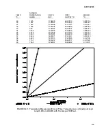
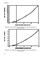
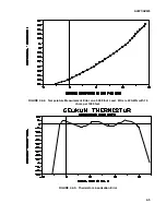
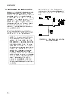
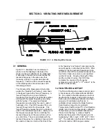
(see Figure 2.2-1 through 2.2-4).  The
linearization error is 

±

0.15

ο

C (see Figure 2.2-5)

over the range from -5 to +60

o

C.  The precision

of the bridge resistors (

±

0.1%) results in a

tolerance of 

±

0.03

o

C.  The accuracy of the

datalogger's voltage measurement (

±

0.015%)

results in a tolerance of 

±

0.01

o

C.  The

temperature coefficient of the bridge resistors
(10 ppm/

o

C) results in a tolerance of

±

0.0003

o

C/

o

C.

Errors four, five, and six mentioned above are
all less than 

±

0.03

o

C each and can probably be

ignored.  The wire resistance is primarily an
offset error and its affect on the pressure
measurement is removed by the initial
calibration.  Errors caused by the change in wire
resistance due to temperature, thermistor
interchangeability, and the linearization error are
not removed by the initial calibration.

Ignoring the offset errors, the remaining
temperature accuracy is expected to be about

±

0.7

o

C.  The temperature correction for the

vibrating wire measurement is typically less than
0.05 psi/

o

C.  A 

±

0.7

o

C temperature error would

result in a 0.035 psi (±

1

.0 inch H2O) error on a

50 psi Full Scale range.

The thermistor, Dale Electronics part number
1C3001-B3 is the standard with an
interchangeability of 

±

0.5

o

C.  The optional

thermistor, Dale Electronics part number
1C3001-C3 has an inter-changeability of

±

0.2

o

C.  Both of the above thermistors have the

same resistance vs. temperature relationship as
the YSI thermistor number 44005.

The following table shows the relationship
between temperature and resistance, volts,
CR10 output, and linearization error.

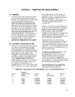
TABLE 2.2-1.  Temperature vs. Thermistor Resistance, V, 

o

C, and Linearization Error

SENSOR

TEMP

RESISTANCE,

VOLTS

CR10

ERROR

o

C     

OHMS            

OUT    

OUTPUT,

o

C

o

C         

 -5

12700

0.668449

-5.09136

-0.09136

 -4

12050

0.692520

-4.02248

-0.02248

 -3

11440

0.716743

-2.98315

0.016846

 -2

10860

0.741399

-1.95557

0.044427

 -1

10310

0.766400

-0.93843

0.061560

Содержание AVW4

Страница 1: ...RUCTION MANUAL Use of the AVW1 and AVW4 with Geokon Model 4500 Vibrating Wire Piezometers and Pressure Transducers Revision 1 92 C o p y r i g h t c 1 9 8 7 1 9 9 2 C a m p b e l l S c i e n t i f i c I n c ...

Страница 2: ...warranties expressed or implied including warranties of merchantability or fitness for a particular purpose CAMPBELL SCIENTIFIC INC is not liable for special indirect incidental or consequential damages Products may not be returned without prior authorization The following contact information is for US and International customers residing in countries served by Campbell Scientific Inc directly Aff...

Страница 3: ...MEASUREMENT 3 1 General 3 1 3 2 Multiplier and Offset 3 1 3 3 Swept Frequency Start and End 3 2 3 4 Resolution vs of cycles 3 3 3 5 Temperature Correction 3 3 3 6 Delay Between Measurements 3 4 4 THE AVW1 4 1 General 4 1 4 2 Sensor Hook Up 4 1 4 3 Well Monitoring Example 4 1 5 THE AVW4 5 1 General 5 1 5 2 Sensor Hook Up 5 2 5 3 Datalogger Programming 5 2 6 THE AVW1 AND A MULTIPLEXER Not yet availa...

Страница 4: ... Measurement Error on a 3000 Foot Lead 2 4 2 2 4 Temperature Measurement Error on a 5000 Foot Lead 2 5 2 2 5 Thermistor Linearization Error 2 5 2 3 1 Direct Measurement of the Geokon Thermistor 2 6 3 1 1 A Vibrating Wire Sensor 3 1 4 1 1 The AVW1 4 1 4 2 1 Hook up to AVW1 4 1 4 3 1 Well Monitoring Example 4 2 5 1 1 The AVW4 5 1 5 2 1 Hook up for AVW4 5 2 A 1 Pressure Conversion Chart A 1 B 1 1 AVW...

Страница 5: ...ll Geokon s manual should be consulted for information on sensor selection and installation Geokon s address and phone number are 48 Spencer Street Lebanon NH 03766 603 448 1562 1 1 SENSOR SELECTION The vibrating wire sensors may be purchased as either vented or sealed sensors The vented sensors have a small hollow vent tube that connects the hollow chamber behind the diaphragm to the atmosphere T...

Страница 6: ... some cases there is no measured reference In order to obtain the correct offset under these conditions lower the sensor to a point just above the water level and wait 5 minutes Use the multiplier an offset of 0 0 and the temperature correction function determined in Sections 3 2 and 3 5 to obtain a reading Record the reading Solve equation 3 2 3 for the new offset by plugging in the reading in th...

Страница 7: ...to 60oC The precision of the bridge resistors 0 1 results in a tolerance of 0 03oC The accuracy of the datalogger s voltage measurement 0 015 results in a tolerance of 0 01oC The temperature coefficient of the bridge resistors 10 ppm oC results in a tolerance of 0 0003oC oC Errors four five and six mentioned above are all less than 0 03oC each and can probably be ignored The wire resistance is pri...

Страница 8: ...05785 0 057855 21 3583 1 304393 21 06127 0 061275 22 3426 1 326119 22 06310 0 063105 23 3277 1 347418 23 06048 0 060484 24 3135 1 368363 24 05747 0 057474 25 3000 1 388888 25 05167 0 051679 26 287 1 408926 26 04042 0 040428 27 2750 1 428571 27 02901 0 029014 28 2633 1 447932 28 02396 0 023968 29 2523 1 466619 29 00577 0 005777 30 2417 1 485089 29 99901 0 00098 31 2317 1 502945 30 98300 0 01699 32 ...

Страница 9: ... 53 965 1 794687 53 09674 0 096746 54 929 6 1 803855 54 08849 0 088499 55 895 8 1 812697 55 07032 0 070322 56 863 3 1 821281 56 04819 0 048193 57 832 2 1 829571 57 01651 0 016519 58 802 3 1 837613 57 97896 0 02103 59 773 7 1 845372 58 92977 0 07022 60 746 3 1 852867 59 86962 0 13037 FIGURE 2 2 1 Temperature Measurement Error at Three Temperatures as a Function of Lead Length Wire is 22 AWG with 16...

Страница 10: ... 4 FIGURE 2 2 2 Temperature Measurement Error on a 1000 foot Lead Wire is 22 AWG with 16 ohms per 1000 feet FIGURE 2 2 3 Temperature Measurement Error on a 3000 foot Lead Wire is 22 AWG with 16 ohms per 1000 feet ...

Страница 11: ...AVW1 AVW4 2 5 FIGURE 2 2 4 Temperature Measurement Error on a 5000 foot Lead Wire is 22 AWG with 16 ohms per 1000 feet FIGURE 2 2 5 Thermistor Linearization Error ...

Страница 12: ...his manual covers AVW1 s with serial number 1093 and up plus serial numbers 1002 1034 1040A 1041 1042 1051 1052 1055 1057 1058 1059 1069 1071 1073 1076 1080 1084 1086 1087 1088 1088A 1089A 1090A 1091A and 1092A This manual also covers AVW4s with serial number 1045 and up plus serial numbers 1034 and 1038 These serial numbers mark a change in circuitry that changes the excitation voltage for the te...

Страница 13: ...ery short time The wire will vibrate with the resonant frequency for a relatively long period of time and as it does so it will cut the lines of flux in the plucking and pickup coils inducing the same frequency on the lines to the CR10 After waiting for the non resonant frequencies to die out 20 ms the CR10 accurately measures how much time it takes to receive a user specified number of cycles Kno...

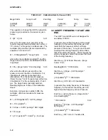
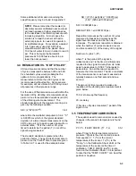
Страница 14: ...und on the Calibration Sheet Example Using sensor number 3998 the multiplier offset and equation for pressure would be M 1000 digits kHz2 0 0151 psi digit M 15 1 psi kHz2 B 0 0 psi 0 0151 psi digit 9431 digits B 142 4 psi P 15 1 psi kHz2 X kHz2 142 4 psi 3 3 SWEPT FREQUENCY START AND END The AVW1 and AVW4 were not designed for use below 1000 Hz In general the starting frequency of the swept freque...

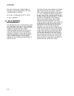
Страница 15: ...s timed to determine the period T in ms of the signal being measured The standard deviation is greater when the period is shorter The period is shortest at zero pressure so the Period at zero pressure given in Table 3 2 1 is used for the example below SD 2 15 1psi kHz2 0 00015ms 500 325 6us 1000us ms 3 SD 0 00026246 psi RESOLUTION 0 00078738 psi Resolution improves as the number of cycles measured...

Страница 16: ...e required they can be done one of two ways With the AVW4 the repetitions parameter must be set to 2 The instructs the CR10 to excite both sensors delay 20 ms measure the first sensor and then measure the second sensor There is no delay or re application of the excitation between the measurements Back to back measurements require that the sum of the number of cycles measured on each sensor not exc...

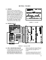
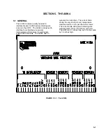
Страница 17: ...inches high The silk screening for the AVW1 is shown below FIGURE 4 1 1 The AVW1 4 2 SENSOR HOOK UP FIGURE 4 2 1 Hook up to AVW1 4 3 WELL MONITORING EXAMPLE In this example the vibrating wire sensor is used to monitor the Distance from the lip of the well to the water surface in a 150 foot well The water level is expected to stay within 40 to 80 feet of the lip so the 50 psi pressure sensor is pla...

Страница 18: ...feet The following is a sample program that measures the temperature and frequency of the vibrating wire sensor and stores the temperature oC pressure psi temperature corrected pressure psi correction factor psi temperature corrected pressure feet of H2O and Distance from the lip to the water surface feet in Input Locations 1 6 respectively This example assumes the sensor has been connected as sho...

Страница 19: ... P37 Z X F 01 4 X Loc T To C 02 0698 F Temp Coeff 03 4 Z Loc T To C 06 P33 Z X Y 01 2 X Loc PRESS psi 02 4 Y Loc T To C 03 3 Z Loc Pt psi 07 P37 Z X F Converts psi to negative ft H20 01 3 X Loc Pt psi 02 2 3067 F 03 5 Z Loc Pt FEET H20 08 P34 Z X F Adds the Offset to the negative of the Reading to obtain the Distance from lip of the well to water surface 01 5 X Loc Pt FEET H20 02 102 06 F OFFSET 0...

Страница 20: ...AVW1 AVW4 4 4 This is a blank page ...

Страница 21: ...g wire sensors temperature and pressure to eight single ended CR10 channels The AVW4 has no quiescent current drain The current drain during the very short 2 4 ms temperature measurement is 4 mA per channel or lower The current drain during each vibrating wire measurement 170 ms to 500 ms is 32 mA The AVW4 is 6 7 inches long by 2 9 inches wide by 1 4 inches high FIGURE 5 1 1 The AVW4 ...

Страница 22: ...rometric pressure only and is used to remove atmospheric pressure changes from the readings on the other three sensors This example assumes the sensors have been connected as shown in the sensor hookup diagram Program AVW4 CR10 USED TO MEASURE 4 GEOKON SENSORS THE FIRST SENSOR SERVES AS A BAROMETER AND IS SUBTRACTED FROM THE OTHER THREE TO MEASURE THREE WATER PRESSURES IN PSI EVERY FIVE MINUTES 1 ...

Страница 23: ...4 09 0698 B4 06 P87 Beginning of Loop TEMPERATURE CORRECTION 01 00 Delay 02 4 Loop Count 07 P34 Z X F ASSUMES CALIBRATION TEMP 24oC 01 1 X Loc TEMP C 1 02 24 F 03 17 Z Loc T To C 1 08 P36 Z X Y 01 13 X Loc Cpsi C 1 02 17 Y Loc T To C 1 03 17 Z Loc T To C 1 09 P33 Z X Y 01 5 X Loc psi 1 02 17 Y Loc T To C 1 03 9 Z Loc Pt psi 1 10 P95 End FOLLOWING THREE INSTRUCTIONS SUBTRACT THE BAROMETRIC PRESSURE...

Страница 24: ...AVW1 AVW4 5 4 This is a blank page ...

Страница 25: ...A 1 APPENDIX A PRESSURE CONVERSION CHART ...

Страница 26: ...This is a blank page ...

Страница 27: ...B 1 APPENDIX B SCHEMATICS AND STUFFING CHARTS FOR AVW1 AND AVW4 ...

Страница 28: ...APPENDIX B SCHEMATICS AND STUFFING CHARTS FOR AVW1 AND AVW4 B 2 ...

Страница 29: ...APPENDIX B SCHEMATICS AND STUFFING CHARTS FOR AVW1 AND AVW4 B 3 ...

Страница 30: ...APPENDIX B SCHEMATICS AND STUFFING CHARTS FOR AVW1 AND AVW4 B 4 ...

Страница 31: ...APPENDIX B SCHEMATICS AND STUFFING CHARTS FOR AVW1 AND AVW4 B 5 ...

Страница 32: ...APPENDIX B SCHEMATICS AND STUFFING CHARTS FOR AVW1 AND AVW4 B 6 This is a blank page ...

Страница 33: ... How many times do we have to change the half period by 1 clock cycle to cover the frequency range 1 F1 2 1 2400 2 208333 ms half period 1 F2 2 1 3100 2 161290 ms half period Change in half period 208333 161290 047043 ms of clock cycle increments to cover the 047043 ms half period range is 047043 ms 0008138 ms 57 81 freq increments How much time is there between frequency increments to cover the f...

Страница 34: ...This is a blank page ...

Страница 35: ...This is a blank page ...

Страница 36: ... campbellsci com br suporte campbellsci com br Campbell Scientific Canada Corp CSC 11564 149th Street NW Edmonton Alberta T5M 1W7 CANADA www campbellsci ca dataloggers campbellsci ca Campbell Scientific Ltd CSL Campbell Park 80 Hathern Road Shepshed Loughborough LE12 9GX UNITED KINGDOM www campbellsci co uk sales campbellsci co uk Campbell Scientific Ltd France Miniparc du Verger Bat H 1 rue de Te...

Отзывы: