background image

Automatic Weather Station with UT20/UT30 Tower 

2-12 

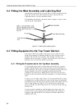
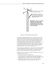
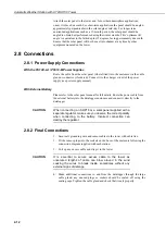
Attach the solar panel to the tower and, for northern hemisphere applications, 
orient it to face due south. For short-term applications the panel should be angled 
approximately perpendicular to the solar angle at mid-day. For longer term 
unattended applications such as a 12-month period, the solar panel should be 
angled to obtain best performance during the winter months. This ‘optimum tilt 
angle’ is equivalent to the latitude plus 15 degrees, facing permanently due south. 
Ensure that the solar panel will not be cast into shadow at any time by other 
equipment mounted on the tower. 

2.8  Connections 

2.8.1  Power Supply Connections 

With the PS12E-LA / PS512-M Power Supplies 

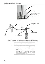
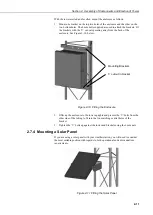
Route the cable from the solar panel (where fitted) into the enclosure via the cable 
gland or connector (if ordered). Connect it to the charger circuit of the power 
supply (see power supply manual). 

With External Battery 

Please refer to the solar panel manual for full details. Route the power cable from 
the external battery into the datalogger enclosure and connect it directly to the 
datalogger. 


When  connecting  an  SOP18  or  a  solar  panel  supplied with a 
separate regulator, make sure you observe the correct polarity 
when  connecting  to  the  battery.  Incorrect  connection  can 
destroy the regulator. 

2.8.2  Final Connections 

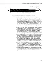
1.  Secure all grounding wire and sensor cables to the tower with cable ties. 

2.  Fit the sensor plugs into the sockets on the base of the enclosure following the 

connection diagram supplied with each station. 

3.  Coil up any excess cable and strap it to the tower. 

It  is  essential  to  secure  excess  cable  to  the  tower  as 
unsecured  lengths  of  cable  can  blow  around  in  the  wind 
causing  the  wires  to  break  inside,  sometimes  without  any 
external signs of damage. 

4.  Make  additional  connections  to  and  from  the  datalogger  through  the  large 

cable  gland;  any  unused  plugs  or  sockets  should  be  sealed  off  using  the     
sealing caps. Tighten the cable gland and check that it seals properly.  

CAUTION 

CAUTION 

Содержание Automatic Weather Station

Страница 1: ...Automatic Weather Station with UT20 or UT30 Tower Issued 27 3 17 Copyright 2002 2017 Campbell Scientific Ltd CSL 164 INSTRUCTION MANUAL...

Страница 2: ......

Страница 3: ...under guarantee or not Please state the faults as clearly as possible and if the product is out of the guarantee period it should be accompanied by a purchase order Quotations for repairs can be give...

Страница 4: ......

Страница 5: ...t for recycling Any batteries contained within the product or used during the products life should be removed from the product and also be sent to an appropriate recycling facility Campbell Scientific...

Страница 6: ......

Страница 7: ...ore beginning work Wear a hardhat and eye protection and take other appropriate safety precautions while working on or around tripods and towers Do not climb tripods or towers at any time and prohibit...

Страница 8: ......

Страница 9: ...Oasis Effect I 2 I 3 Obstructions I 3 I 4 The Effects of an Urban Environment I 3 I 5 Checking and Preparation I 3 Section 1 Site Preparation and Assembly of the Tower 1 1 1 1 Introduction 1 1 1 2 De...

Страница 10: ...ks 2 8 2 6 Tower Erection 2 8 2 6 1 Fitting Optional Guy Wires to Ground Anchors 2 9 2 7 Mounting Low Level Sensors and Other Equipment 2 10 2 7 1 Pyranometer 2 10 2 7 2 Temperature Relative Humidity...

Страница 11: ...2 3 Attaching the Top Tower Section 2 4 2 4 Sighting Along the Tower to Check the Magnetic Bearing 2 5 2 5 Weighting the Wind Sensor Perpendicular to the Ground 2 6 2 6 Both Mounting Arms and Sensors...

Страница 12: ......

Страница 13: ...ents The choice of location for your tower based weather station will depend on a number of circumstances and these are thoroughly discussed in Section I 1 of this manual After selecting a suitable si...

Страница 14: ...nts while the tower is on the ground is given in Section 2 of this manual DO NOT CLIMB the tower whether guyed or unguyed for any reason Carry out the fitting and maintenance of all high level sensors...

Страница 15: ...ribes several factors which can affect the results obtained Please read through this information before deciding where to locate your AWS The descriptions in this introductory section are general rule...

Страница 16: ...found in the meteorological literature I 2 1 The Clothesline Effect The clothesline effect in its simplest form describes the effect of air passing from dry unvegetated surfaces to moist vegetated su...

Страница 17: ...n has a net radiometer be particularly cautious when siting it in a built up area as building temperature sky view factors and other variables affect the short wave and long wave components of the cal...

Страница 18: ...r Rustproofing compound for threads An adjustable spanner A range of standard and Phillips screwdrivers A compass for wind direction orientation Cable ties supplied A set of Allen hex keys at least a...

Страница 19: ...g the concrete base foundations Materials to make the foundations wood formers concrete mixture etc Wire rope cutter if using guy ropes on your installation A length of rope to assist in raising the t...

Страница 20: ......

Страница 21: ...the tower where this is required and where the optional guying kit is provided 1 1 Introduction The UT20 and UT30 are tubular aluminium towers with two UT20 or three UT30 main sections plus a mast as...

Страница 22: ...igure 1 2 UT30 Tower Assembly with Enclosure Solar Panel and a Typical Range of Sensors Middle Section Mast Assembly Top Section Middle Section Bottom Section Hinged Mounting Base Assembly concreted i...

Страница 23: ...ual gives full instructions for guying the tower where required Do not attempt to climb the structure whether guyed or not either to do initial installation or to carry out routine maintenance of comp...

Страница 24: ...need to consider the positions of the guy anchors please refer to Section 1 6 below NEVER place any aluminium tower section directly into a concrete base The corrosive effects of the concrete on alum...

Страница 25: ...ole periodically check that the tower is vertical using a spirit level and make adjustments as necessary Allow three to four days for the concrete to cure Figure 1 3 Bottom Tower Section and Base Inst...

Страница 26: ...g Stand the base and tower section upright and orient for the proper tilt direction see Figure 1 4 Install the base to the roof using three lag bolts or other anchors appropriate for the application s...

Страница 27: ...stake and scribe a circle with a 3 6 metre radius for UT20 or a 5 2 metre radius for UT30 3 Choose a tilt direction for the tower 4 From the centre point walk in the opposite direction and drive a st...

Страница 28: ...level A pair of pliers Having previously installed the base and bottom tower section remove both bolts from the rear tower leg Remove the lower bolts and loosen the upper bolts in the other two legs...

Страница 29: ...mbly 1 9 Figure 1 7 Fitting the Tower Sections 1 8 Fitting AWS Components and Erecting the Tower Section 2 of this manual details the fitting of sensors and other equipment and the final erection and...

Страница 30: ......

Страница 31: ...evel to deter vandalism and give better exposure to light but this would make periodic maintenance such as cleaning more difficult and you may wish to mount such instruments at a lower level accessibl...

Страница 32: ...ollowing the advice given below in order to reduce the likelihood of measurement errors This section gives details of mounting the pyranometer to the top mast assembly This is the recommended mounting...

Страница 33: ...r fitting onto the main tower structure The following section gives details of mounting the pyranometer on the top mast assembly Section 2 7 describes mounting it on the tower structure at a lower lev...

Страница 34: ...r on the top mast assembly as described above you should mount the arm to face approximately south relative to the tower and always bear in mind and attempt to minimise any possible shading effects of...

Страница 35: ...ed with the 011E arm to allow this In addition a nylon washer is supplied which can be used to stop the spacer and screw falling out of the mounting arm during installation 6 Weight the fin of the win...

Страница 36: ...correctly fitted as described above and in the sensor manuals Failure to do so can lead to false measurements or damage to the sensors 2 Do not attempt to remove the rotor of the wind speed sensor or...

Страница 37: ...and in Appendix A 2 3 4 018E Arm Wind Monitor and Pyranometer This arm is a combination of the 016E and 017E and is assembled in the same way as described for those arms starting with the pyranometer...

Страница 38: ...the position of the enclosure Always allow extra wiring for ease of assembly Attach the wiring to the tower with the cable ties Remember if you make an error you will probably have to lower the tower...

Страница 39: ...hile holding the tower vertical attach the guy wires to the eye end of the turnbuckles using one thimble and three U bolts per guy wire as shown in Figure 2 7 The U bolts should be fitted as shown at...

Страница 40: ...screws 2 7 2 Temperature Relative Humidity Probe The sensor can be inserted into the radiation shield before it is mounted on the tower This is done by loosening the large hexagonal nut and inserting...

Страница 41: ...gure 2 10 below Figure 2 10 Fitting the Enclosure 2 Offer up the enclosure to the tower uprights and present the V bolts from the other side of the tubing to fit into the two matching central holes of...

Страница 42: ...ual With External Battery Please refer to the solar panel manual for full details Route the power cable from the external battery into the datalogger enclosure and connect it directly to the datalogge...

Страница 43: ...Drive the spike into the ground using the Allen screw as a driving head Position the spike as close as possible to the base of the tower 2 Remove the Allen screw and screw the second spike into the s...

Страница 44: ...her station is installed at a site where frequent direct lightning strikes are likely Campbell Scientific recommends that you seek the advice of a specialist lightning protection company 2 10 Maintena...

Страница 45: ...ction 1 2 10 3 Inspection After a few days check that the tower is secure and level Check the guy wires where fitted and all bolts At least every year and preferably every six months check the tower f...

Страница 46: ...nsors is necessary you may have to remove the top section of the mast and proceed as outlined in Section 2 3 of this manual After all necessary maintenance has been carried out re erect the tower foll...

Страница 47: ...er Guide use the datalogger program as follows 1 Set up the link between your PC and the datalogger The simplest method is a direct link using the SC32B opto isolated interface or an SC929 Interface C...

Страница 48: ...ll the functions of PC200W PC400 or LoggerNet are contained in the User Guide for the software Campbell Scientific dataloggers can be programmed from a computer without using the datalogger support so...

Страница 49: ...tic north is easily corrected by adding or subtracting the difference between the two readings as explained below Maps are always drawn in relation to the true north pole and ordnance survey maps will...

Страница 50: ...h the magnetic north bearing to set the wind sensor to true north as explained in Section 2 3 of this manual NOTE Declination angles for True North to the West of Magnetic North are subtracted from 36...

Страница 51: ......

Страница 52: ...W Edmonton Alberta T5L 4X4 CANADA www campbellsci ca dataloggers campbellsci ca Campbell Scientific Centro Caribe S A CSCC 300N Cementerio Edificio Breller Santo Domingo Heredia 40305 COSTA RICA www c...

Отзывы: