background image

+

_

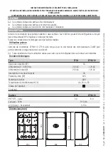
DELAY 2M

OP. TIME

A.C.T.

ON

DIP

p. 

9

 - M

an

u

al


FA

0

0

67

9

-E

N

 v.


1

- 1

2

/2

0

17 - © C

A

M

E S

.p.

A

. - T

h

e c

onte

nts of th

is

 m

an

u

al

 m

ay b

e c

h

an

g

ed, at a

ny ti

m

e, a

n

d w

ith

ou

t n

oti

ce

.

DIP-SWITCH

Description of functions

AUTOMATIC CLOSING

Automatic closing active (1 OFF - Deactivated)

OPEN-STOP-CLOSE-STOP

OPEN-STOP-CLOSE-STOP (sequential) function from control device (NO contact) and from 
radio transmitter fitted with AF card.

OPEN-CLOSE-INVERT

OPEN-CLOSE-INVERT (step-step) function from control device (NO contact) and from radio 
transmitter fitted with AF card.

SAFETY TEST

At each opening or closing command, the card checks whether the photocells are working 
properly (3 OFF - Deactivated)

DELETING USERS

Deleting one or more users (4 OFF - Deactivated)

Settings

Functions

Trimmer

Description of functions

A.C.T.

AUTOMATIC CLOSING TIME

It sets the open gate's waiting time. Once this time elapses, a closing maneuver is automatically 
performed.
The waiting time can be adjusted to between 1 and 120 seconds.

 The automatic closing does not activate if the safety devices are triggered due to obstacle detection, 

after a total Stop or if the current is missing.

OP. TIME

OPERATING TIME

This sets the gearmotors' operating time.
The operating time can be adjusted to between 15 and 120 seconds.

 Setting the time to the minimum enables the maintained action function and disables the radio-

based controls.

DELAY 2M

MOTOR M2 CLOSING DELAY TIME

After a closing command or after an automatic closing, the leaf of gearmotor (M2) starts with a delay 
compared to gearmotor (M1) for an adjustable time of between 3 and 10 seconds.

FUNCTIONS AND SETTINGS

Содержание ZF1N110

Страница 1: ...IT Italiano EN English FR Français RU Pусский FA00679M04 QUADRO COMANDO PER MOTORIDUTTORI A 120 V O 230 V ZF1N110 ZF1N MANUALE DI INSTALLAZIONE ...

Страница 2: ...NE Quadro comando per cancelli a due ante battenti Funzioni impostabili con i DIP e regolabili con i trimmer Tutte le connessioni e i collegamenti sono protetti da fusibili rapidi Destinazione d uso Il quadro comando ZF1N110 ZF1N è stato progettato per il comando dei motoriduttori CAME per cancelli a battente a uso residenziale o condominiale Ogni installazione e uso difformi da quanto indicato ne...

Страница 3: ...venire sul quadro comando togliere la tensione di linea e se presenti scollegare le batterie Verifiche preliminari Prima di procedere all installazione del quadro comando è necessario verificare che il punto di fissaggio sia in una zona protetta dagli urti che le superfici di ancoraggio siano solide e che il fissaggio venga fatto con elementi idonei viti tasselli ecc alla superficie prevedere nella ret...

Страница 4: ...EC 53 IEC Per collegamento antenna utilizzare cavi tipo RG58 fino a 10 m Qualora i cavi abbiano lunghezza diversa rispetto a quanto previsto in tabella si determini la sezione dei cavi sulla base dell effettivo assorbimento dei dispositivi collegati e secondo le prescrizioni indicate dalla normativa CEI EN 60204 1 Per i collegamenti che prevedano più carichi sulla stessa linea sequenziali il dimen...

Страница 5: ...ssori 24 V AC max 20 W 120 V o 230 V AC 50 60 Hz INSTALLAZIONE Fissaggio del quadro comando Fissare la base del quadro in una zona protetta con viti e tasselli Si consiglia di usare viti con testa cilindrica 6 x 70 mm Forare sui fori presfondati 18 e 20 mm sotto la base del quadro Attenzione a non danneggiare la scheda elettronica Inserire i pressacavi con i tubi corrugati per il passaggio dei cav...

Страница 6: ...li di modifica in qualsiasi momento senza obbligo di preavviso Collegamento dei motoriduttori Motoriduttore M2 120 V AC o 230 V AC ritardato in chiusura Motoriduttore M1 120 V AC o 230 V AC ritardato in apertura Limitatore di coppia motore Per variare la coppia motore spostare il faston indicato su una delle 4 posizioni 1 min 4 max versione 120 V AC se disponibile ...

Страница 7: ...il pulsante di comando o un altro dispositivo di comando Se non utilizzato cortocircuitare il contatto Funzione APRE CHIUDE INVERSIONE passo passo da dispositivo di comando contatto NO In alternativa con il DIP 2 in ON è possibile attivare il comando APRE STOP CHIUDE STOP sequenziale Elettroserratura Collegamento elettroserratura a 12 V Potenza max 15 W Dispositivi di segnalazioni Uscita collegame...

Страница 8: ...non usato Dispositivi di sicurezza Fotocellule Ingresso per dispositivi di sicurezza tipo fotocellule Riapertura durante la chiusura In fase di chiusura del cancello l apertura del contatto provoca l inversione del movimento fino alla completa apertura Se non vengono utilizzate le fotocellule cortocircuitare il contatto 2 C1 Collegamento dei dispositivi di sicurezza test sicurezza A ogni comando di...

Страница 9: ...lato da 15 a 120 secondi Regolando il tempo al minimo si abilita la funzione di azione mantenuta e si disabilitano i radiocomandi DELAY 2M TEMPO RITARDO IN CHIUSURA DEL MOTORE M2 Dopo un comando di chiusura o dopo una chiusura automatica l anta del motoriduttore M2 parte in ritardo rispetto al motoriduttore M1 per un tempo regolabile da 3 a 10 secondi Funzioni Regolazioni DIP Descrizione delle fun...

Страница 10: ...a agli appositi morsetti Inserire la scheda AF sul connettore della scheda elettronica Prima di inserire la scheda AF è OBBLIGATORIO TOGLIERE LA TENSIONE DI LINEA e se presenti scollegare le batterie Scheda AF Inserimento di un utente É possibile registare fino ad un massimo di 50 utenti Tenere premuto il tasto di programmazione PROG sulla scheda elettronica Il LED di programmazione lampeggia Prem...

Страница 11: ... secondi premere il tasto del trasmettitore dell utente da cancellare Il LED lampeggia velocemente per un secondo a segnalare l avvenuta cancellazione dopodichè si spegne Riposizionare il DIP 4 in OFF Tasto PROG LED di programmazione Cancellazione di tutti gli utenti Posizionare il DIP 4 in ON Tenere premuto il tasto PROG sulla scheda elettronica per 10 secondi circa Il LED di programmazione esegu...

Страница 12: ...e opportuno verificare le normative specifiche vigenti nel luogo d installazione I componenti dell imballo cartone plastiche etc sono assimilabili ai rifiuti solidi urbani e possono essere smaltiti senza alcuna difficoltà semplicemente effettuando la raccolta differenziata per il riciclaggio Altri componenti schede elettroniche batterie dei trasmettitori etc possono invece contenere sostanze inquinan...

Страница 13: ...CONTROL PANEL FOR 120 V OR 230 V GEARMOTORS ZF1N110 ZF1N INSTALLATION MANUAL EN English FA00679 EN ...

Страница 14: ...is manual is forbidden Technical data Type ZF1N ZF1N110 Protection rating IP 54 Power supply V 50 60 Hz 230 AC 120 AC Input voltage motor V 230 AC 120 AC Consumption in stand by mode mA 40 Maximum power W 320 Casing material ABS Operating temperature C 20 to 55 Apparatus class Weight Kg Fuses ZF1N ZF1N110 Line 5 A 8 A Card 315mA Accessories 3 15 A KEY This symbol shows which parts to read carefull...

Страница 15: ...mpliant with the installation rules It should completely cut off the power supply according to category III surcharge conditions make sure that any connections inside the container ones that ensure continuity to the protection circuit are fitted with additional insulation with respect to those of other electrical parts inside set up suitable tubes and conduits for the electric cables to pass throug...

Страница 16: ...ht 2 x 0 5 mm 2 Command and control devices 2 x 0 5 mm 2 Safety devices 2 x 0 5 mm 2 When powered at 120 V or 230 V and used outdoors use H05RN F type cables that comply with 60245 IEC 57 IEC whereas indoors use H05VV F type cables that are 60227 IEC 53 IEC compliant Use RG58 cable up to 10 m long to connect the antenna If cable lengths differ from those specified in the table establish the cable ...

Страница 17: ...Fastening the control panel Fasten the control panel in a protected area using suitable screws and dowels Only use 6 x 70 mm cylinder head screws Drill through the pre drilled holes 18 and 20 mm under the control panel s base Be careful not to damage the control board Enter the cable gland with the corrugated tubes for threading the electrical cables 120 V or 230 V AC 50 60 Hz Accessories 24 V AC ...

Страница 18: ...anual may be changed at any time and without notice 120 V AC version if available Motor s torque limiter To vary the motor torque move the faston as shown to one of the four positions 1 min 4 max Gearmotor M1 120 V AC or 230 V AC delayed when opening Gearmotor M2 120 V AC or 230 V AC delayed when closing Connecting the gearmotors ...

Страница 19: ...sed Output for connecting the flashing signal light Contact rated for 120 V or 230 V AC 25 W max Signaling devices Electrolock connection at 12 V Maximum power 15 W Electric lock OPEN CLOSE INVERT function step step from control device NO contact Alternatively by setting DIP switch 2 to ON you can activate the OPEN STOP CLOSE STOP sequential command STOP button NC contact For stopping the gate whil...

Страница 20: ...ng the safety devices i e the safety test At each opening and closing command the control board checks the efficacy of the safety devices such as photocells Any anomalies will inhibit all commands For this type of connection enable the function by setting DIP switch 3 to ON Safety devices Photocells Input for safety devices such as photocells Reopening during closing When the gate is closing openi...

Страница 21: ... 4 OFF Deactivated Settings Functions Trimmer Description of functions A C T AUTOMATIC CLOSING TIME It sets the open gate s waiting time Once this time elapses a closing maneuver is automatically performed The waiting time can be adjusted to between 1 and 120 seconds The automatic closing does not activate if the safety devices are triggered due to obstacle detection after a total Stop or if the c...

Страница 22: ...ming LEDflashing Press any key on the transmitter you want to memorize The LED stays on to indicate thatmemorization has been successful AF card MANAGING USERS BY RADIO CONTROL Preliminary operations Connect the RG58 cable antenna cable to the corresponding terminals Fit the AF card into the control board connector Before fitting the AF card you MUST CUT OFF THE MAIN POWER SUPPLY and remove any emer...

Страница 23: ...rage length flashes about 5 seconds and quick flashes about 2 seconds until it it switches off Reset DIP switch 4 to OFF Programming LED PROG key Deleting a single user Set DIP switch 4 to ON Keep pressed the PROG button on the control board The programming LED flashes Within five seconds press the button on the transmitter of the user you wish to delete The LED will flash quickly for one second to sig...

Страница 24: ...sure you comply with local laws before dismantling and disposing of the product The packaging materials cardboard plastic and so on should be disposed of as solid household waste and simply separated from other waste for recycling Whereas other components control boards batteries transmitters and so on may contain hazardous pollutants These must therefore be disposed of by authorized certified prof...

Страница 25: ...ARMOIRE DE COMMANDE POUR MOTORÉDUCTEURS EN 120 V OU 230 V ZF1N110 ZF1N MANUEL D INSTALLATION FR Français FA00679 FR ...

Страница 26: ...ées dans ce manuel sont interdites Données techniques Type ZF1N ZF1N110 Degré de protection IP 54 Alimentation V 50 60 Hz 230 AC 120 AC Alimentation moteur V 230 AC 120 AC Absorption en mode veille mA 40 Puissance max W 320 Matériau du boîtier ABS Température de fonctionnement C de 20 à 55 Classe de l appareil Poids Kg Fusibles ZF1N ZF1N110 Ligne 5 A 8 A Carte 315 mA Accessoires 3 15 A LÉGENDE Ce ...

Страница 27: ...nformément aux règles d installation un dispositif de déconnexion omnipolaire spécifique pour le sectionnement total en cas de surtension catégorie III s assurer que les éventuelles connexions à l intérieur du boîtier réalisées pour la continuité du circuit de protection sont bien dotées d une isolation supplémentaire par rapport aux autres parties conductrices internes prévoir des tuyaux et des co...

Страница 28: ...ande 2 x 0 5 mm 2 Dispositifs de sécurité 2 x 0 5 mm 2 En cas d alimentation en 120 V ou 230 V et d une utilisation en extérieur adopter des câbles H05RN F conformes à la norme 60245 IEC 57 IEC en intérieur utiliser par contre des câbles H05VV F conformes à la norme 60227 IEC 53 IEC Pour la connexion de l antenne utiliser des câbles RG58 jusqu à 10 m Si la longueur des câbles ne correspond pas aux...

Страница 29: ...N Fixation de l armoire de commande Fixer la base de l armoire dans une zone protégée à l aide de vis et de chevilles Il est conseillé d utiliser des vis à tête cylindrique 6 x 70 mm Percer les trous préforés 18 et 20 mm sous la base de l armoire Avoir soin de ne pas endommager la carte électronique Introduire les passe câbles avec gaines annelées pour le passage des câbles électriques 120 V ou 23...

Страница 30: ...e subir des modifications à tout moment et sans aucun préavis version 120 VAC si disponible Limiteur de couple moteur Pour varier le couple moteur déplacer la cosse indiquée sur une des 4 positions 1 min 4 max Motoréducteur M1 120 VAC ou 230 VAC retardé à l ouverture Motoréducteur M2 120 VAC ou 230 VAC retardé à la fermeture Connexion des motoréducteurs ...

Страница 31: ... Portée contact 120 V ou 230 VAC 25 W max Dispositifs de signalisation Connexion serrure de verrouillage électrique 12 V Puissance max 15 W Serrure de verrouillage électrique Fonction OUVERTURE FERMETURE INVERSION pas à pas depuis un dispositif de commande contact NO Il est également possible avec DIP 2 sur ON d activer la commande OUVERTURE ARRÊT FERMETURE ARRÊT séquentielle Bouton d ARRÊT contac...

Страница 32: ...é test sécurité La carte contrôle l efficacité des dispositifs de sécurité ex photocellules à chaque commande d ouverture ou de fermeture Les anomalies quelles qu elles soient désactivent les commandes Pour ce type de connexion activer la fonction avec DIP 3 sur ON Dispositifs de sécurité Photocellules Entrée pour dispositifs de sécurité type photocellules Réouverture durant la fermeture Durant la...

Страница 33: ... Désactivée Réglages Fonctions Trimmers Description des fonctions TFA TEMPS DE FERMETURE AUTOMATIQUE Permet de régler le délai d attente du portail en position d ouverture Après écoulement de ce délai une manœuvre de fermeture est automatiquement effectuée Le temps d attente peut être réglé entre 1 et 120 secondes L intervention des dispositifs de sécurité en cas de détection d un obstacle après u...

Страница 34: ... voyant de programmation led clignote Appuyer sur une des touches de l émetteur à mémoriser Le voyant restera allumé pour signaler l exécution effective de la mémorisation Carte AF GESTION DES UTILISATEURS PAR COMMANDE RADIO Opérations préliminaires Connecter le câble RG58 de l antenne aux bornes spécifiques Insérer la carte AF sur le connecteur de la carte électronique Avant d installer la carte A...

Страница 35: ...clignotements moyens environ 5 s lents environ 5 s et rapides environ 2 s jusqu à l extinction Positionner à nouveau le DIP 4 sur OFF Voyant de programmation Touche PROG Élimination d un seul utilisateur Positionner le micro interrupteur DIP 4 sur ON Maintenir enfoncée la touche PROG sur la carte électronique Le voyant de programmation led clignote Appuyer dans les 5 secondes qui suivent sur la to...

Страница 36: ...es normes spécifiques en vigueur sur le lieu d installation Les composants de l emballage carton plastiques etc sont assimilables aux déchets urbains solides et peuvent être éliminés sans aucune difficulté en procédant tout simplement à la collecte différenciée pour le recyclage D autres composants cartes électroniques piles des émetteurs etc peuvent par contre contenir des substances polluantes Il...

Страница 37: ...БЛОК УПРАВЛЕНИЯ ЭЛЕКТРОПРИВОДАМИ 120 В ИЛИ 230 В ZF1N110 ZF1N ИНСТРУКЦИЯ ПО МОНТАЖУ RU Русский FA00679 RU ...

Страница 38: ...характеристики Модель ZF1N ZF1N110 Класс защиты IP 54 Напряжение электропитания В 50 60 Гц 230 120 Электропитание двигателя В 230 120 Потребление в режиме ожидания мА 40 Макс мощность Вт 320 Материал корпуса ABS Диапазон рабочих температур C 20 55 Класс устройства Масса кг Плавкие предохранители ZF1N ZF1N110 Входной 5 A 8 A Плата 315 мА Аксессуары 3 15 A УСЛОВНЫЕ ОБОЗНАЧЕНИЯ Этот символ обозначает...

Страница 39: ...ы Для подключения сети электропитания необходимо предусмотреть автоматический выключатель с расстоянием между контактами не менее 3 мм обеспечивающий защиту от перенапряжения III степени Убедитесь в том чтобы между соединениями кабеля и другими токопроводящими частями была предусмотрена дополнительная изоляция Приготовьте лотки и каналы для проводки кабеля гарантирующие надежную защиту от механиче...

Страница 40: ...па 2 x 0 5 мм 2 Устройства управления 2 x 0 5 мм 2 Устройства безопасности 2 x 0 5 мм 2 При напряжении 120 В или 230 В и применении снаружи необходимо использовать кабели типа H05RN F соответствующие 60245 IEC 57 IEC в помещениях следует использовать кабели типа H05VV F соответствующие 60227 IEC 53 IEC Для подключения антенны используйте кабель типа RG58 длиной до 10 м Если длина кабеля отличается...

Страница 41: ...вание блока управления в защищенном от механических повреждений месте с помощью винтов и дюбелей Рекомендуется использовать винты с цилиндрической головкой 6 x 70 мм Рассверлите отверстия в предварительно размеченных местах 18 и 20 мм под основанием блока управления Будьте предельно осторожны чтобы не повредить плату управления Вставьте в отверстия гермовводы с гофрированными трубами для проводки ...

Страница 42: ...ожет быть изменено в любое время без предварительного уведомления версия 120 В при наличии Регулировка усилия привода Для изменения крутящего момента установите указанный коннектор типа фастон в одно из 4 положений мин 1 макс 4 Привод M1 120 В или 230 В замед ленное открывание Привод M2 120 В или 230 В замед ленное закрывание Подключение приводов ...

Страница 43: ...25 Вт Устройства сигнализации Выход для подключения электрозамка 12 В Макс мощность 15 Вт Электрозамок Функция ОТКРЫТЬ ЗАКРЫТЬ ИЗМЕНИТЬ НАПРАВЛЕНИЕ пошаговый режим с по мощью устройства управления нормаль но разомкнутые контакты В качестве альтернативы можно выбрать режим ОТ КРЫТЬ СТОП ЗАКРЫТЬ последователь ный установив DIP переключатель 2 в положение ВКЛ Кнопка СТОП нормально замкнутые кон такты...

Страница 44: ...аче команды на открывание или закрывание плата управления проверяет работоспо собность устройств безопасности например фотоэлементов При обнаружении неисправности в работе фотоэлементов любая команда управления блокируется Для этого типа подключения необходимо активировать функцию DIP 3 Устройства безопасности Фотоэлементы Контакты подключения устройств безопасности например фотоэлементов Открыван...

Страница 45: ...зователей 4 OFF Отключена Регулировки Функции Регулировки Описание функций и режимов работы A C T ВРЕМЯ АВТОМАТИЧЕСКОГО ЗАКРЫВАНИЯ Регулирует время ожидания ворот в открытом положении По истечении заданного времени происходит автоматическое закрывание Время ожидания может составлять от 1 до 120 секунд Функция автоматического закрывания ворот не работает при срабатывании устройств безопасности в ре...

Страница 46: ...я Светодиодный индикатор мигает Нажмите на кнопку программируемого пульта ДУ Если светодиодный индикатор горит ровным светом программирование выполнено успешно Плата радиоприемника AF УПРАВЛЕНИЕ ПОЛЬЗОВАТЕЛЯМИ С ПУЛЬТАМИ ДУ Предварительные работы Подключите антенну кабелем RG58 к соответствующим контактам Вставьте плату AF в разъем платы управления ОБЯЗАТЕЛЬНО ОТКЛЮЧИТЕ ЭЛЕКТРОПИТАНИЕ и отсоединит...

Страница 47: ... средней частотой около 5 секунд медленно около 5 секунд и затем быстро около 2 секунд до полного выключения Установите DIP 4 обратно в положение ВЫКЛ Светодиодный индикатор программирования Кнопка PROG Удаление отдельного пользователя Установите DIP 4 в положение ВКЛ Нажмите и удерживайте в нажатом положении кнопку PROG на плате управления Светодиодный индикатор мигает В течение 5 секунд нажмите ...

Страница 48: ...щим законодательством местности в которой производилась эксплуатация изделия Упаковочные компоненты картон пластмасса и т д твердые отходы утилизируемые без каких либо специфических трудностей Необходимо просто разделить их так чтобы они могли быть переработаны Другие компоненты электронные платы батарейки пультов дистанционного управления и т д напротив могут содержать загрязняющие вещества Они д...

Отзывы: