


C
O
M
Rallentam.
Velocità
Max.
Max. Med. Min. Min.
DIS. 27370
ON
2
1
3
4
5
6
7
8
9 10
N
M
PT
F
FC
FA
N
L
L27
L1T
E
+10
-11
1
2
3
5
7
C1
C5
GND
TX
RX
9
8
7 10
11
1
2
12 13
3
6
5
4
14
18
16
15
17
Bl
u
p.
12
- M
anu
al
F
A
0
111
6
-E
N
- 0
1/
2
0
18 - © C
A
M
E S
.p
.A
. - T
ransla
te
d o
riginal inst
ru
ct
io
ns
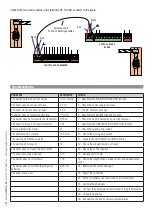
FUSE TABLE
ZL38
- Line
3.15 A-F
- Card
630 mA-F
- Gearmotor
10 A-F
- Accessories
2 A-F
DESCRIPTION OF PARTS
1. Accessories fuse
2. Line fuse
3. Control-board fuse
4. Motor fuse
5. Terminals for control and safety devices
6. AF card slot
7. SENS trimmer
8. ACT Trimmer
9. DIP-SWITCH
10. Programming button
11. Programming warning LED
12. Speed and slow-down adjusting connectors
13. Battery charger (LB38) connectors
14. Command type selection jumper
15. Transformer
16. Power supply terminals
17. Terminal for gearmotors
18. Limit-switch terminals
CONTROL PANEL
⚠
Caution! Before working on the control panel, cut off the mains power supply and remove any batteries.
Power supply to the control panel and control devices: 24 V AC/DC.
Use DIP switches to set functions and the trimmer for adjustments.
All wiring connections are quick-fuse protected.


