background image

9

A

ll t

h

e d

at

a a

n

d i

n

fo

rm

at

io

n c

o

n

ta

in

ed h

er

ei

n

 i

s c

o

n

si

d

er

ed

 s

u

b

je

ct to c

h

an

g

e a

t a

n

y t

im

e a

n

d a

t o

u

r d

is

cr

et

io

n

ENGLISH

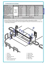
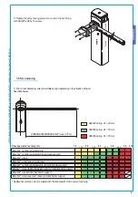
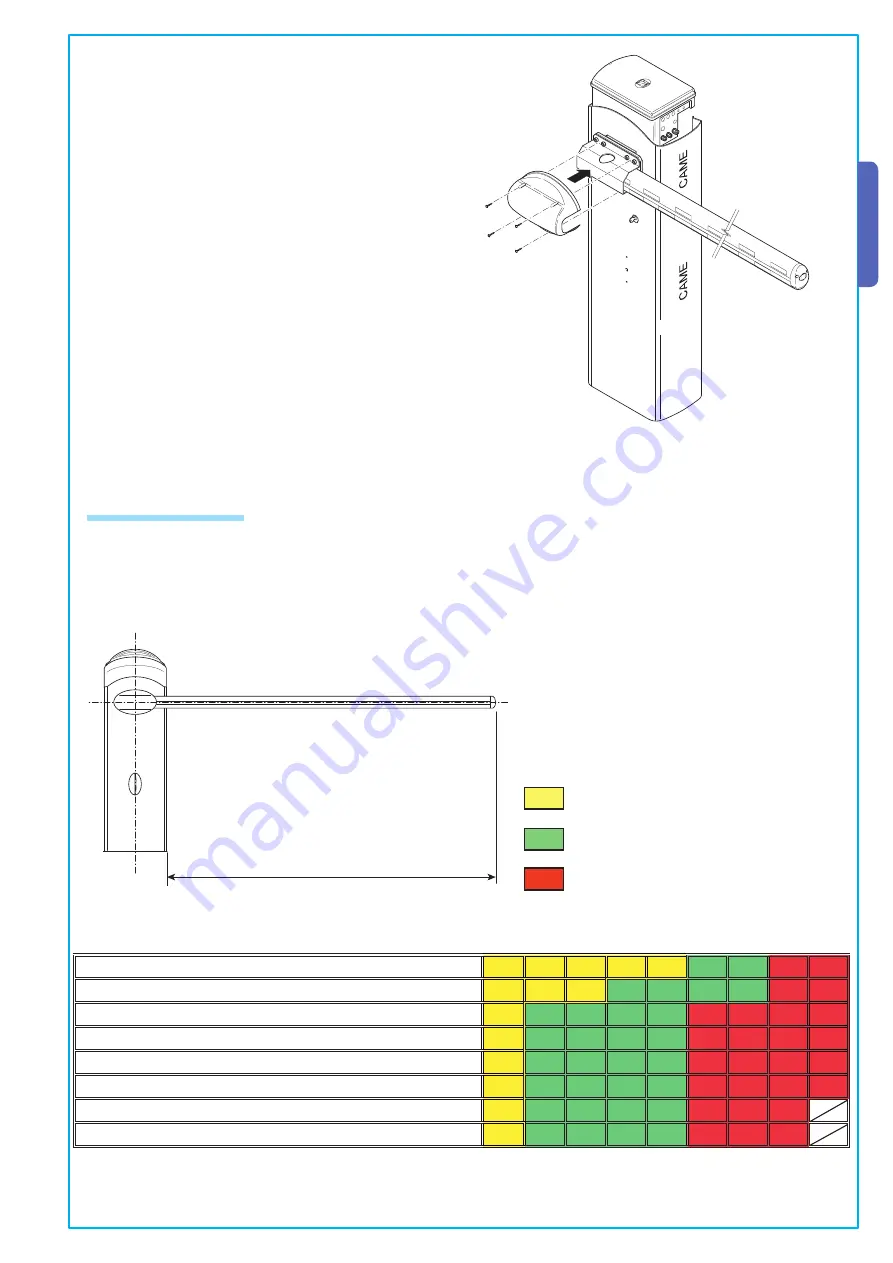
1) Prior to bar balancing, select a suitable spring depending on the situation at hand. 
See table below.

Bare bar* + shock-resistant profile

Bare bar* + shock-resistant profile and luminous cord

Bare bar* + rack

Bare bar* + luminous cord and rack

Bare bar* + shock-resistant profile and mobile barrier support

Bare bar* + shock-resistant profile, luminous cord and mobile barrier support

Bare bar* + rack and mobile barrier support

Bare bar* + luminous cord, rack and mobile barrier support

Passage clearance lamp (m)                                                          1.5     

1.75   

  2.0     

2.25

     2.5     

2.75

     3.0     

3.25     

3.5    3.75 

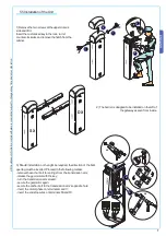
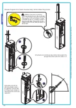
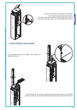
7) Tighten the anti-shearing protection cover to the bar fitting 
with UNI6954 Ø3.9x19 screws.

5.6 Bar balancing

* By Bare bar we mean a bar complete with the transparent slot cover and end plug.

PASSAGE CLEARANCE LAMP (max. 3.75 m)

G02040 spring  Ø

e

 = 40 mm

G04060 spring  Ø

e

 = 50 mm

G06080 spring  Ø

e

 = 55 mm

Содержание G4041

Страница 1: ...AUTOMATION FOR STREET BARRIERS GARD 4 SERIES G4041 G4041I INSTALLATION MANUAL ...

Страница 2: ...o the GARD 4 automation system 002 RSE Board for combined battery operation control and or compass for ZG5 control board 001 G02801 Flashing dome lamp 001 G02802 Support for mounting the photoelectric cell DIR onto the cabinet not applicable to barriers with bar and rack and or mobile foot 001 G02803 Luminous cord for movement signalling 001 G02804 Luminous cord connecting cable 001 G02807 Fixed b...

Страница 3: ...r semioval aluminium bar 5 Anti shearing protection cover 6 Sheet steel or stainless steel cabi net with galvanized and painted finish 7 Inspection hatch 8 Gearmotor 9 ABS container for electric board with transformer 1 G03750 Semioval aluminium bar painted white L 4 m 2 G03752 Oval aluminium bar painted white L 4 m 3 G02040 Ø40 yellow balancing spring 4 G04060 Ø50 green balancing spring 5 G06080 ...

Страница 4: ...ions inside the case made for protection circuit continuity are allowed as long as they include additional insulation with respect to other internal drive parts Install suitable tubes and ducts for electric cable passage to guarantee protection against mechanical damage Installation must be carried out by expert qualified personnel and in full observance of regulations in force 5 Installation 5 1 ...

Страница 5: ...le 20 30 m 230V 2F power supply FROR CEI 20 22 CEI EN 50267 2 1 3G x 1 5 mm2 3G x 2 5 mm2 3G x 4 mm2 230V motor power supply 3 x 1 mm2 3 x 1 5 mm2 3 x 2 5 mm2 24V 230V flashing lamp 2 x 0 5 mm2 2 x 1 mm2 2 x 1 5 mm2 Photoelectric cells TX 2 x 0 5 mm2 2 x 0 5 mm2 2 x 0 5 mm2 Photoelectric cells RX 4 x 0 5 mm2 4 x 0 5 mm2 4 x 0 5 mm2 24V power supply accessory 2 x 0 5 mm2 2 x 0 5 mm2 2 x 1 mm2 Contr...

Страница 6: ...re a hole to house the fixing base and prepare sheath tubes from the branch pit for the connections 4 Remove the nuts and washers from the threaded screws position the cabinet on the base in correspondence with the 4 threaded screws and secure with the nuts and washers Note We recommend installing the cabinet with the inspection hatch facing the internal area 3 Fill the hole with concrete and imme...

Страница 7: ... 2 The barrier is designed to be installed on the left of the gateway as seen from inside 3 Should installation on the right be required the direction of the bar s opening must be inverted Proceed in the following manner remove the anchor bolt for springs from the transmission arm release the gearmotor with the key turn the transmission arm around secure the gearmotor again secure the anchor bolt ...

Страница 8: ... length of the bar cut the bar slot to the same length and insert it in the bar s conduit a procedure that should be carried out on both sides Insert the shock resistant profile and cut excess length Lastly secure the bar end plug with the screws provided 4 Position the middle plate between the fitting plate and the bar fitting cover and put in one UNI 5931 M8x20 screw without tightening it to fac...

Страница 9: ...resistant profile and mobile barrier support Barebar shock resistantprofile luminouscordandmobilebarriersupport Bare bar rack and mobile barrier support Bare bar luminous cord rack and mobile barrier support Passage clearance lamp m 1 5 1 75 2 0 2 25 2 5 2 75 3 0 3 25 3 5 3 75 7 Tighten the anti shearing protection cover to the bar fitting with UNI6954 Ø3 9x19 screws 5 6 Bar balancing By Bare bar ...

Страница 10: ...an anchor nut 4 Hook the tie rod to the anchoring bracket release the gearmotor and manually turn the spring to increase or decrease traction until the bar rests at 45 WARNING The release procedure may constitute a hazard for the user when for whatever reason the bar is fixed improperly to the housing during assembly or the bar is cracked or broken in an accident and so on the tension springs no l...

Страница 11: ... loose when the bar is in the vertical position at rest the spring is tight when the bar is in the horizontal position tense 5 7 ZG5 or ZG6 Electric board installation 1 Loosen the three screws in the container cover located in the upper part of the unit 2 Insert the board in the container and fasten it with the screws provided carry out all the electrical connections see the dedicated technical d...

Страница 12: ...s of steps to make sure of the bar s correct opening and closing positions and then if necessary proceed to the adjustment of the dampers Warning For greater safety and better unit performance the bar s opening and closing operations should be carried out with the inspection hatch closed 1 Execute the closing operation adjust the open bar s position by turning the free damper clockwise to increase...

Страница 13: ...g and closing adjustment tighten the locking nuts under the dampers 5 Insert the inspection hatch and close it 4 After making adjustments and settings from the control panel put the container lid in place and secure with screws 6 Insert the protection dome on the upper part of the unit and secure with the two UNI6955 Ø3 9x13 screws provided ...

Страница 14: ...ry measure and in case of intensive use we re commend periodic checks every 6 months on the state of the electric wire connected to the motor the spring bar balance the tightness of the nuts and the proper oiling of the sliding points between fixed and mobile parts All checks must be recorded in a dedicated record book 6 Maintenance 6 2 Problem solving In its premises CAME CANCELLI AUTOMATICI S p ...

Страница 15: ...le parts of the following Standards 98 37 CE 98 79 CE MACHINERY DIRECTIVE 98 336 CEE 92 31 CEE ELECTROMAGNETIC COMPATIBILITY DIRECTIVE 73 23 CEE 93 68 CE LOW VOLTAGE DIRECTIVE 89 106 CEE CONSTRUCTION PRODUCTS DIRECTIVE EN 13241 1 EN 12635 EN 61000 6 2 EN 12453 EN 12978 EN 61000 6 3 EN 12445 EN 60335 1 EN 60204 1 IMPORTANT WARNING Do not use the equipment specified here above before completing the ...

Страница 16: ...Cod 119GT81 ver 0 2 06 06 CAME CANCELLI AUTOMATICI CAME UNITED KINGDOM LTD UNIT 3 ORCHARD BUSINESS PARK TOWN STREET SANDIACRE NOTTINGHAM NG10 5BP U K Tel 0044 115 9210430 Fax 0044 115 9210431 ...

Отзывы:

Похожие инструкции для G4041