


- pag.
- pag.
- pag.
- pag.
- pag.
15
15
15
15
15
- english -
- english -
- english -
- english -
- english -
2
1
3
4
5
6
7
8
9 10
0
Rall.
Vel.
7
4
C
O
M
Velocità
Speed
Vitesse
Geschw.
Velocidad
Rallentamento
Deceleration
Ralentissement
Geschw.
Abnahme
Deceleración
"B"
"A"
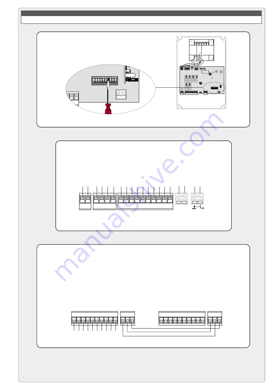
2) Wire the electrical connections only on the terminal board
for the pilot motor in the normal.
CONNECTIONS FOR 2 COMBINED MOTORS CONTROLLED TOGETHER
ZL37B CONTROL PANEL
1) On one of the two control panels, set
Dip
7
to
ON
in order to select the motor
controlled externally (slave).
Slave motor 2° terminal block
3) Connect the two control panels using the interlock terminals as shown in
the figure.
Pilot motor 1° terminal block
E +10-11 1 2
C1C5
7
3 5
INTERBLOCCO
E +10-11 1 2
C1C5
7
3 5
INTERBLOCCO
FA FC F PT
M N
E +10-11 1 2
C1C5
7
3 5
L1 L2