CAME ATS30AGS Скачать руководство пользователя страница 22

p. 

4

 - M

an

u

al


FA

0

0

67

9

-E

N

 v.


1

- 1

2

/2

0

17 - © C

A

M

E S

.p.

A

. - T

h

e c

onte

nts of th

is

 m

an

u

al

 m

ay b

e c

h

an

g

ed, at a

ny ti

m

e, a

n

d w

ith

ou

t n

oti

ce

.

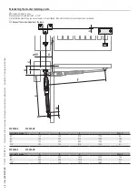
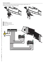
Cable types and minimum thicknesses
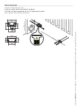
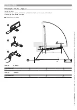
Tools and materials

Make sure you have all the tools and materials you will need for installing in total safety and in compliance with 
applicable regulations. The fi gure shows some of the equipment installers will need.

Connection

cable length

< 20 m

20 < 30 m

Control panel 120 / 230 V AC (1P+N+PE)

3G x 1.5 mm

2

3G x 2.5 mm

2

Gearmotor 120 / 230 V AC

4G x 1.5 mm

2

4G x 2.5 mm

2

TX Photocells

2 x 0.5 mm

2

RX photocells

4 x 0.5 mm

2

Flashing light

2 x 0.5 mm

2

Command and control devices

2 x 0.5 mm

2

Safety devices

2 x 0.5 mm

2

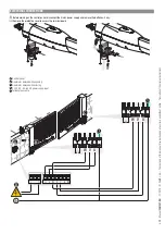
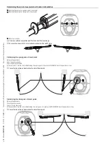
When powered at 120 V or 230 V and used outdoors, use H05RN-F-type cables that comply with 60245 

IEC 57 (IEC); whereas indoors, use H05VV-F-type cables that are 60227 IEC 53 (IEC) compliant.

Use RG58 cable up to 10 m long to connect the antenna.

 If cable lengths differ from those specified in the table, establish the cable sections depending on the actual 

power draw of the connected devices and according to the provisions of regulation CEI EN 60204-1.

For multiple, sequential loads along the same line, the dimensions on the table need to be recalculated 

according to the actual power draw and distances. For connecting products that are not contemplated in this 
manual, see the literature accompanying said products

Содержание ATS30AGS

Страница 1: ...Gearmotor for swing gates ATS30AGS ATS50AGS ATS30AGR ATS50AGR INSTALLATION MANUAL FA01337 EN EN English...

Страница 2: ...1 2 3 1 2 3 4...

Страница 3: ...upply that is compliant with the installation rules It should completely cut off the power supply according to category III surcharge conditions Demarcate the entire site properly to prevent unauthori...

Страница 4: ...egies Simply follow these brief disposal guidelines DISPOSING OF THE PACKAGING The packaging materials cardboard plastic etc can be disposed of easily as solid urban waste separated for recycling Befo...

Страница 5: ...ed are in millimetres Description 801MP 0050 ATS30AGS Irreversible telescopic gearmotor 230 V for swing gates with Max C 200 mm with leaf up to 3 m and 400 kg Grey RAL7024 801MP 0060 ATS50AGS Irrevers...

Страница 6: ...otor 1 Gate bracket 2 Door to access the end of travel adjustment screws 3 Door to access the release mechanism 4 Sheath connector 5 Post bracket 6 Release key 7 Release cord 8 Cutting hazard labels A...

Страница 7: ...erating cycles MODELS ATS30AGS ATS50AGS ATS30AGR ATS50AGR Cycles hour no 20 20 20 20 Consecutive cycles no 10 10 10 10 The cycles calculation applies to gates that are professionally installed free of...

Страница 8: ...r fitting the operator and accessories varies depending on the area where it is installed It is up to the installer to find the most suitable solution The drawings refer to a gearmotor installed on th...

Страница 9: ...o 90 or 120 First determine where the gate bracket needs to be positioned then where the post bracket needs to be positioned Respect the values indicated in the table A C B 60 60 E F 5 ATS30AGS ATS30A...

Страница 10: ...riginal instructions Fastening the brackets Secure the post bracket with plugs and screws If the post is made of metal the post bracket must be welded to it The holes on the bracket fixing plate allow...

Страница 11: ...at any time and without notice Translation of the original instructions Fastening the gearmotor Lubricate all moving parts on the operator A The self locking nut must be loosely tightened so as not t...

Страница 12: ...ons ELECTRICAL CONNECTIONS Before working on the control panel disconnect the mains power supply and remove the batteries if any Remove the protective cover to access the terminal board A Control pane...

Страница 13: ...roswitch 10 mm in either direction turn the rod 20 times Determining the opening end of travel points Release the gearmotor Open the gate manually Send an opening command At the same time turn the rod...

Страница 14: ...hing the bracket fastening points Close the gate manually First determine where the gate bracket needs to be positioned then where the post bracket needs to be positioned Respect the values indicated...

Страница 15: ...ons Electrical connections Before working on the control panel disconnect the mains power supply and remove the batteries if any Remove the protective cover to access the terminal board A Control pane...

Страница 16: ...d of travel points Release the gearmotor Open the gate manually Send an opening command At the same time turn the rod for determining the opening end of travel point ANTICLOCKWISE until the gearmotor...

Страница 17: ...p 17 Manual FA01337 EN 11 2019 CAME S p A The contents of this manual may be changed at any time and without notice Translation of the original instructions FINAL OPERATIONS 1 2...

Страница 18: ...f the system is not used for long periods of time e g for installations at sites with seasonal closures disconnect the power supply When the power supply is reconnected check the system is working cor...

Страница 19: ...CONTROL PANEL FOR 120 V OR 230 V GEARMOTORS ZF1N110 ZF1N INSTALLATION MANUAL EN English FA00679 EN...

Страница 20: ...s manual is forbidden Technical data Type ZF1N ZF1N110 Protection rating IP 54 Power supply V 50 60 Hz 230 AC 120 AC Input voltage motor V 230 AC 120 AC Consumption in stand by mode mA 40 Maximum powe...

Страница 21: ...pliant with the installation rules It should completely cut off the power supply according to category III surcharge conditions make sure that any connections inside the container ones that ensure con...

Страница 22: ...2 x 0 5 mm 2 Command and control devices 2 x 0 5 mm 2 Safety devices 2 x 0 5 mm 2 When powered at 120 V or 230 V and used outdoors use H05RN F type cables that comply with 60245 IEC 57 IEC whereas in...

Страница 23: ...astening the control panel Fasten the control panel in a protected area using suitable screws and dowels Only use 6 x 70 mm cylinder head screws Drill through the pre drilled holes 18 and 20 mm under...

Страница 24: ...nual may be changed at any time and without notice 120 V AC version if available Motor s torque limiter To vary the motor torque move the faston as shown to one of the four positions 1 min 4 max Gearm...

Страница 25: ...ed Output for connecting the ashing signal light Contact rated for 120 V or 230 V AC 25 W max Signaling devices Electrolock connection at 12 V Maximum power 15 W Electric lock OPEN CLOSE INVERT functi...

Страница 26: ...g the safety devices i e the safety test At each opening and closing command the control board checks the efficacy of the safety devices such as photocells Any anomalies will inhibit all commands For...

Страница 27: ...4 OFF Deactivated Settings Functions Trimmer Description of functions A C T AUTOMATIC CLOSING TIME It sets the open gate s waiting time Once this time elapses a closing maneuver is automatically perfo...

Страница 28: ...ing LED ashing Press any key on the transmitter you want to memorize The LED stays on to indicate thatmemorization has been successful AF card MANAGING USERS BY RADIO CONTROL Preliminary operations Co...

Страница 29: ...verage length ashes about 5 seconds and quick ashes about 2 seconds until it it switches off Reset DIP switch 4 to OFF Programming LED PROG key Deleting a single user Set DIP switch 4 to ON Keep press...

Страница 30: ...ure you comply with local laws before dismantling and disposing of the product The packaging materials cardboard plastic and so on should be disposed of as solid household waste and simply separated f...

Отзывы: