background image

23

3

7

4

1

2

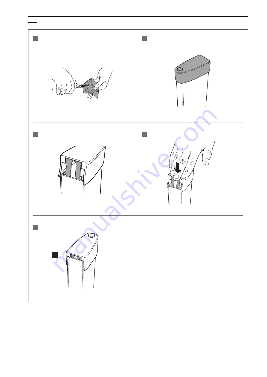
4.4   Montage des capuchons

Préparer le capuchon du bas : 
retirer le plot de drainage

Positionner le capuchon en correctement

Enfoncer le clip de fixation jusqu’à la butée

Positionner le clip de fixation

Position finale correcte

Содержание 8050456085153

Страница 1: ...causare decesso lesioni gravi e seri danni materiali Profilo sensibile di sicurezza Terminale Terminali di contatto Profilo di attivazione Profilo in alluminio Cavo di collegamento Resistenze di term...

Страница 2: ...evono rientrare preferibilmente tra 0 a 40 C Sono possibili temperature di stoccaggio da 30 a 60 C purch per breve tempo ad es durante il trasporto 3 Assemblaggio dei bordi sensibili 3 1 Panoramica de...

Страница 3: ...questo motivo dopo aver disimballato e rimosso la copertura protettiva di un terminale occorre operare con particolare cura e pulizia fino a quando il terminale non completamente inserito Tenere le a...

Страница 4: ...nza Collegare il connettore della resistenza e il cavo azionare il generatore di segnali in diversi punti Generatore di segnali azionato 500 Ohm Generatore di segnali non azionato con resistenze di te...

Страница 5: ...gio del profilo portante Il profilo portante deve essere montato su una superficie piana Se necessario foro per cavo 4 Montaggio dei generatori di segnali bordi sensibili Profilo di attivazione precon...

Страница 6: ...profilo portante Innestare il primo lato del profilo di attivazione a raso nelle due estremit del profilo portante e inserirlo nel profilo portante in modo uniforme procedendo verso il centro Gli elem...

Страница 7: ...erminali Preparare il terminale inferiore rimuovere la pallina di drenaggio e inserirlo Posizionare il terminale in modo adeguato Premere la clip di fissaggio fino in fondo Posizionare la clip di fiss...

Страница 8: ...rdo sensibile Una volta installato bordo sensibile di sicurezza va collegato al dispositivo di controllo 4 5 Controllo dell installazione del generatore di segnali Dopo aver montato il bordo sensibile...

Страница 9: ...e standard would be EN 12978 Safety devices for pow er operated doors and gates Failure to comply with these safety instructions may result in severe or fatal injury and serious damage to property Saf...

Страница 10: ...ween 0 C and 40 C However the components can be stored at temperatures from 30 C to 60 C for short periods of time e g during transport 3 Assembly of contact profiles 3 1 Overview of the individual co...

Страница 11: ...acked a contact end piece and removed the protective cover you should proceed with particular care and ensure that the working environment is kept clean and tidy until it is pressed into place Hold th...

Страница 12: ...te check Resistance measurement Connect the resistor plug and the cable actuate the sensor at several points Sensor actuated 500 ohm Sensor not actuated with 8 2 kOhm resistor plug resistance between...

Страница 13: ...2 3 1 4 1 Overview 4 2 Mounting the mounting profile The mounting profile must be mounted on a flat surface If necessary hole for cable 4 Mounting sensors Preassembled contact profile as described in...

Страница 14: ...mounting profile Tip Use a suitable tool for example a wide spatula for pressing in Push on the profile hard from the front to check that it has been pressed in correctly The contact profile must not...

Страница 15: ...4 1 2 4 4 Mounting end caps Prepare the lower end cap remove the drainage stud Position the end cap correctly Push the fastening clip in as far as the stop Position the fastening clip Correct end pos...

Страница 16: ...ted 500 ohm Sensor not actuated with 8 2 kOhm resistor plug resistance between 8 0 and 9 0 kOhm 5 Commissioning Once the sensor has been installed it must be connected to the control unit The operatin...

Страница 17: ...s curit pour les portes et portails motoris s Le non respect de ces consignes de s curit peut entra ner des blessures graves voire mortelles ainsi que des dommages mat riels importants Profil sensible...

Страница 18: ...res de 30 C 60 C sont toutefois possibles pour une courte dur e par exemple pendant le transport 3 Assemblage de profil s sensibles 3 1 Vue d ensemble des diff rents composants Les profils sensibles d...

Страница 19: ...bout de contact et t sa protection vous devez porter une attention particuli re et vous assurer que l environ nement de travail est maintenu propre et rang jusqu son insertion Maintenir les c t s du p...

Страница 20: ...mesure de la r sistance Raccorder les fiches avec r sistance et c ble appuyer sur le profil sensible diff rents endroits D tecteur activ 500 Ohm D tecteur non activ avec fiche de r sistance 8 2 kOhm...

Страница 21: ...Vue d ensemble 4 2 Montage du profil porteur Le profil porteur doit tre mont sur une surface plane Si n cessaire per age pour le c ble 4 Montage de profil sensible Profil sensible pr assembl comme d...

Страница 22: ...dans le profil porteur en aluminium Conseil Utilisez un outil appropri par exemple une large spatule pour appuyer L embo tement correct est contr l en appuyant avec force de face sur le profil Le prof...

Страница 23: ...ontage des capuchons Pr parer le capuchon du bas retirer le plot de drainage Positionner le capuchon en correctement Enfoncer le clip de fixation jusqu la but e Positionner le clip de fixation Positio...

Страница 24: ...tecteur activ 500 Ohm D tecteur non activ avec fiche de r sistance 8 2 kOhm entre 8 0 et 9 0 kOhm 5 Mise en service Une fois le profil sensible install le raccorder l unit de contr le Les instructions...

Страница 25: ...n f r kraftbet tigte T ren und Tore erw hnt Die Nichtbeachtung dieser Sicherheitshinweise kann zu Tod schwerer K rperverletzung und hohen Sachsch den f hren Sicherheitsleiste Endkappe Kontaktendst ck...

Страница 26: ...und 40 C erfolgen Lagertemperaturen von 30 C bis 60 C sind jedoch kurzzeitig z B w hrend des Transports problemlos m glich 3 Konfektionierung von Schaltprofilen 3 1 bersicht der Einzelkomponenten Sic...

Страница 27: ...ach dem Entpacken und Entfernen der Schutzabdeckung eines Kontak tendst ckes bis dieses fertig aufgepresst ist mit besonderer Sorgfalt und Sauberkeit gearbeitet werden Profilschenkel in spitzem Winkel...

Страница 28: ...tandsmessung Widerstandsstecker und Kabel anschliessen Signalgeber an mehreren Stellen bet tigen Signalgeber bet tigt 500 Ohm Signalgeber unbet tigt mit Widerstandsstecker 8 2 kOhm zwischen 8 0 und 9...

Страница 29: ...2 3 1 4 1 bersicht 4 2 Montage Tr gerprofil Das Tr gerprofil muss auf einer ebenen Fl che montiert werden Wenn n tig Bohrung f r Kabel 4 Montage von Signalgebern Vorkonfektioniertes Schaltprofil gem s...

Страница 30: ...eeignetes Werkzeug verwenden zum Beispiel einen breiten Spachtel Zur Kontrolle des korrekten Einschienens Profil von vorne kr ftig bet tigen Schaltprofil darf an keiner Stelle aus der Aluschiene aussc...

Страница 31: ...4 4 Montage der Endkappen Untere Endkappe vorbereiten Entw sserungsnoppe entfernen Endkappe passend positionieren Befestigungsclip bis zum Anschlag eindr cken Befestigungsclip positionieren Korrekte...

Страница 32: ...gt 500 Ohm Signalgeber unbet tigt mit Widerstandstecker 8 2 kOhm zwischen 8 0 und 9 0 kOhm 5 Inbetriebnahme Nach Installation des Signalgebers ist dieser mit der Signalverarbeitung zu verbinden F r de...

Отзывы: