


Page 4 of 28
CX-33 Advanced Logic Relay Installation Instructions
Section 3B
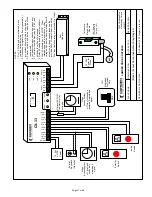
2 Door Timed Airlock
(Mode 2)
Utilizing door position switches (Camden CX-MDC or
equivalent), this mode ensures that only one door in an
airlock will be open at a time. Each output hold time is
adjustable from 1 – 50 seconds. 3 outputs allow for one
of the doors to have an electric lock and a door operator.
(Alternatively, the doors could have locks only and no
operators.)
Refer to
Diagram 2
, (Page 12) for the following connections.
Wire the activating device(s) for Door #1 to DRY 1 terminals.
Wire the activating device(s) for Door #2 to DRY 2 terminals.
Wire the respective door contact switches to Inputs 3 & 4.
(The contact circuit must be closed when the door is closed).
Wire the outputs as shown.. If a lock is not used, set H1 & D1
timers to zero (0.0), and Relay 1 will be ignored.
Once input and output connections are made, program the
unit according to the General Programming Instructions on
page 1, and walk-test the installation. Timing adjustments
may need to be made.
It is NOT recommended to add the “Delay-on-activate”
(or nuisance delay) feature in this mode!
Once the desired operation is achieved, proceed to
Section 4, Pg 9 for
System Inspection Instructions
.
Section 3C
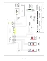
2 Door Latching Airlock
(Mode 3)
Utilizing door position switches, (Camden CX-MDC, or
equivalent) this mode ensures that only one door in an airlock
will be open at a time. Providing the opposite door is closed,
one switch activation will latch open (unlock) the door, and
the second activation on the same input will allow the door
to close (lock). 3 outputs allow for one of the doors to have
an electric lock and a door operator. (Alternatively, the doors
could have locks only and no operators.)
The CX-33 is unique in the industry because it also provides
the ability to add an adjustable “Walk-away” time. If the door
input has been activated but the door has not been opened,
the relay will reset (re-lock). Both doors have their own
respective adjustable timers. (If the time is set to zero, then
this feature is disabled).
Refer to
Diagram 3
, (Page 13) for the following connections.
Wire the activating device(s) for Door #1 to DRY 1 terminals.
Wire the activating device(s) for Door #2 to DRY 2 terminals.
Wire the respective door contact switches to Inputs 3 & 4.
(The contact circuit must be closed when the door is closed).
Wire the outputs as shown. If a lock is not used, set H1 & D1
timers to zero (0.0), and Relay 1 will be ignored.
Once input and output connections are made, program the
unit according to the General Programming Instructions on
page 1, and walk-test the installation. Timing adjustments
may need to be made.
It is NOT recommended to add the “Delay-on-activate”
(or nuisance delay) feature in this mode!
Once the desired operation is achieved, proceed to
Section 4, Pg 9 for
System Inspection Instructions
.
Section 3D
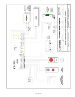
Bi-Directional Door Sequencer
(Mode 4)
This mode sequences all 3 relays in both directions, also
known as bi-directional door sequencing.
A basic 2-door sequencer with just two inputs and two
outputs is shown in
Diagram 4a
(Page 14). A more complex
sequencer utilizing 4 switch inputs, and allowing for one door
with an electric lock is shown in
Diagram 4b
(Page 15).
DRY 1 or WET 1 inputs sequence Relay 1 to Relay 2 to Relay 3.
DRY 2 input sequences Relay 3 to Relay 1 to Relay 2.
Input 3 only sequences Relay 1 to Relay 2, and Input 4 only
activates Relay 3.
If a relay (Relay 1 for example) operation is not desired it
can be turned off by setting the time delays to zero (in this
example H1 & D1).
Once input and output connections are made, program the
unit according to the General Programming Instructions on
page 1, and walk-test the installation. Timing adjustments
may need to be made.
In addition, you can add a “Delay-on-activate” (or nuisance
delay) to this mode by setting time via Step 8 of the Program
Mode. If this feature is used, any input will have to be held
for at least the time indicated on the display
before
the
CX-33 will activate. If this feature is not wanted, set the time
to zero (0.0)
Once the desired operation is achieved, proceed to Section 4,
Pg 9 for
System Inspection Instructions
.
Содержание CX-33
Страница 10: ...Page 10 of 28...
Страница 11: ...Page 11 of 28...
Страница 12: ...Page 12 of 28...
Страница 13: ...Page 13 of 28...
Страница 14: ...Page 14 of 28...
Страница 18: ...Page 18 of 28...
Страница 19: ...Page 19 of 28...
Страница 20: ...Page 20 of 28...
Страница 21: ...Page 21 of 28...
Страница 22: ...Page 22 of 28...
Страница 23: ...Page 23 of 28...


