VORTEX
S I LV E R SE R I ES
3
4
1
2
5
6
USER MANUAL
VORTEX SILVER SERIES V8
P.14
4.1 Screen User Interface
Due to the advanced approach with the absence of any control knobs or
switches, control of all parameters is done via the screen user interface.
4.1.1 Screen User Interface Elements
The screen user interface consists of four buttons and two selection bars.
1 MENU button (
)
- touch to leave the current sreen without changes
- Hot key: touch and hold (≈2 s) to navigate to the Signal Monitor
2 ENTER button (
)
- navigate to the selected menu item, confirm changes
3 A button ( )
- select channel A
4 B button ( )
- select channel B
5 Horizontal Selection Bar (HSB)
- increase/decrease values
6 Vertical Selection Bar (VSB)
- scrolls through menu items
4.1.2 Handle the Selection Bars
-Tip the VSB at the upper half to scroll upwards.
-Tip the VSB at the lower half to scroll downwards.
-Tip the HSB at the left half to decrease values.
-Tip the HSB at the right half to increase values.
4 OPERA
TION
VORTEX
S I LV E R SE R I ES
USER MANUAL
VORTEX SILVER SERIES V8
P.15
4.1.3 Hot key Functions
The Hot key Functions give you a quick access to important setting screens.
The Power Hot key is accessible from all menu levels and screens.
Power Off Hot key:
Touch and hold MENU and ENTER
simultaneously (≈3 s).
Power Off screen will be displayed. Touching again MENU and ENTER
simultaneously will start Power Off-Sequence.
Level Attenuator Hot key (from monitor screens 3.1-3.4):
Touching the HSB opens the Level Attenuator Screen for a quick access
to level adjustments. After adjustment you can step back to the previous
screen by touching the MENU button.
Mute Hot key (from monitor screens 3.2-3.4):
Touching button A or button B
let you directly jump to the Signal Monitor.
Here you can mute/unmute each channel directly by touching button A or
button B again. After adjustment you can step back to the previous screen
by touching the MENU button.
Signal Monitor Hot key
Touch and hold MENU
(≈3 s) let you directly jump to the Signal Monitor.
You can step back to the previous screen by touching the MENU button.
4.2 Power On-Sequence
As soon as the
V8
amplifer is connected to the mains power supply, it will
start the Power On-Sequence. The display will show the
V8
logo followed
by the Power On-Screen.
This is the screen used to switch the amplifier on/off. Please touch MENU
and ENTER simultaneously to switch on the amplifier or touch any of the
touch-sensitive elements to activate the display backlight.
NOTE: Turning the Amplifier off does NOT disconnect the amplifier
from mains.
The switch initiates start-up by activating the current limiting function. As
soon as the power amplifier is connected to the mains power supply, a
voltage is supplied to both the line-filter and the fused input of the control-
lable rectifier. Disconnecting the amplifier from the main power supply can
only be achieved by physically separating the amplifier from the mains by
pulling the mains plug. The mains plug therefore has to be freely acces-
sible. Disconnect the mains plug from the mains during a lightning storm
or when the amplifier remains unused or unsupervised for a prolonged pe-
riod of time. Alternatively, you can disconnect the amplifier from the mains
via an external all-pole disconnection.
If a power cut occurs while the amplifier is switched on, it will restart auto-
matically once the power supply has been restored. All settings prior to the
loss of power will be maintained.
4 OPERA
TION
VORTEX
S I LV E R SE R I ES
USER MANUAL
VORTEX SILVER SERIES V8
P.16
4.3 Indicators
Input Selection LED
Output Mode LED
Clip LED Channel A
Signal LED Channel A
Device Identifier LED
Clip LED Channel B
Signal LED Channel B
DSP LED
Uman LED
4.3.1 Input Selection LED
The status of the bi-coloured (green/red) LED changes between off, green,
and red depending on the selected Input Selection
(see 4.5.1)
.
LED is off
-
Analog Inputs active
LED lit green
-
Digital (Uman) inputs active
LED lit red
-
If Digital with Analog Fallback is selected, the red
Input Mode LED indicates that one of the digital
inputs have failed and will be replaced by analog
backup signal.
4.3.2 Output Mode LED
The status of the bi-coloured (green/orange) LED changes between off,
green, and orange depending on the selected Output Mode
(see 3.3 &
4.5.2)
.
LED is off
-
Dual Channel Operation
LED lit green
- Mono Bridge Operation
LED lit orange - Parallel Mono Operation
4.3.3 Clip LED (Channel A/Channel B)
This LED indicates an overloading of the amplifier when the power output
level is too high.
4.3.4 Signal LED (Channel A/Channel B)
The green Signal LED is illuminated when the voltage level at the output
reaches approx. 4 V; this corresponds to a power of approx. 4 W over a
4
Ω
resistor.
4.3.5 Device Identifier LED
This white coloured LED helps you to identify an amplifier in a large Uman
network. By activating the Identify Device function in Uman software, the
Device Identifer LED of the corresponding amplifier will shine.
4.3.6 DSP LED
The green DSP LED is illuminated when the optional DSP-Board
(see
www.camcoaudio.com for more information)
is installed and routed into
the signal path.
4.3.7 Uman LED
The green Uman LED is illuminated when the amplifier is connected to a
Uman network.
4 OPERA
TION
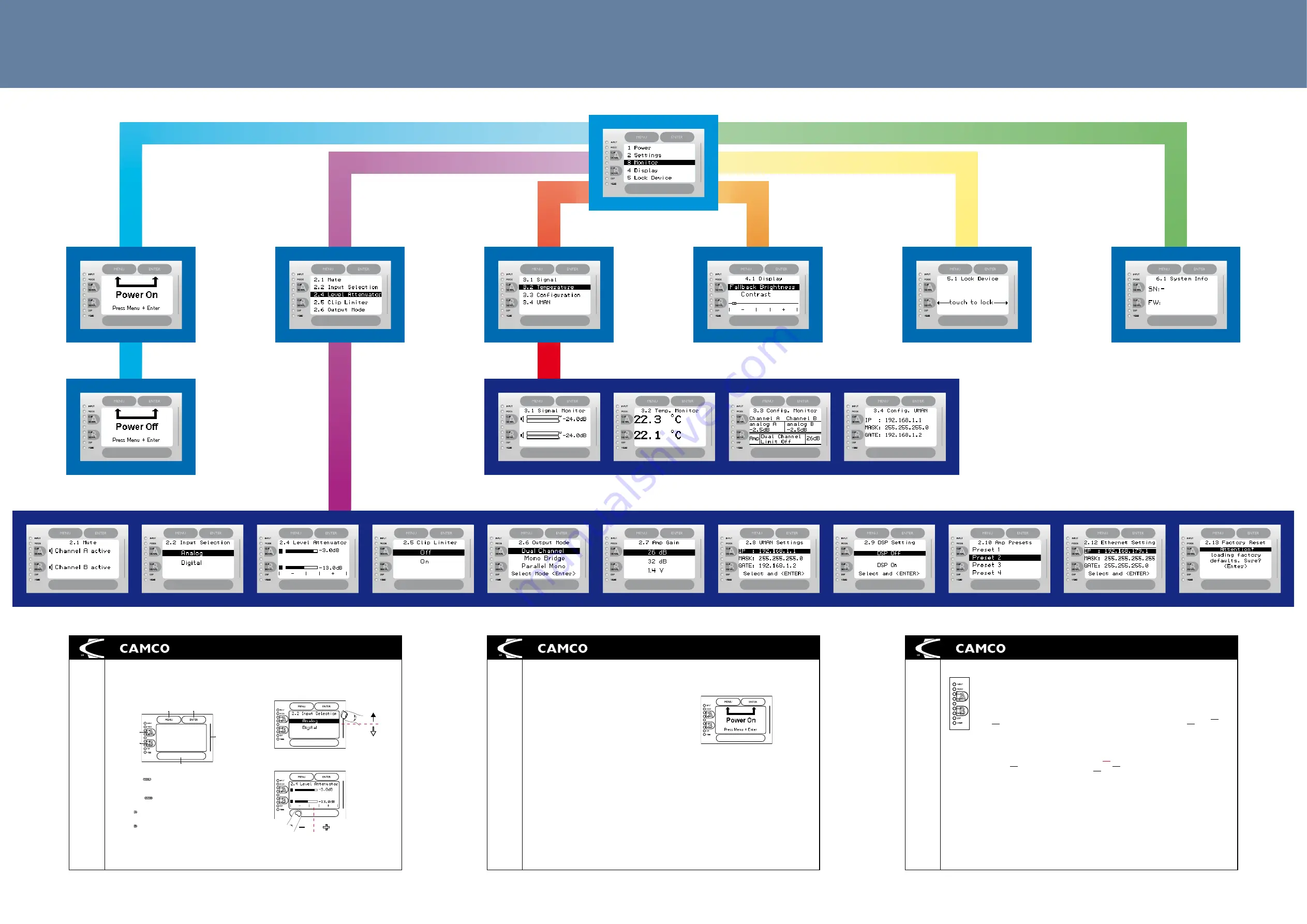
V8 Navigation Guide
version: 2010-11-04 (please visit www.camcoaudio.com for the latest version of this file)
Excerpt from the V8 User Manual. For more details, please consult the V8 User Manual or visit us on www.camcoaudio.com.

