background image

10

Speaker Wire and Stand Installation

   Typically, the 3 meter speaker
cables will connect the front and
center satellites to the Decoder
Amplifier and the 5 meter cables
will connect the rear satellites to
the Decoder Amplifier.  A panel of
twelve self-adhesive labels is
provided to identify each satellite
and subwoofer and the opposite
end of the cable connected to a
satellite and subwoofer.
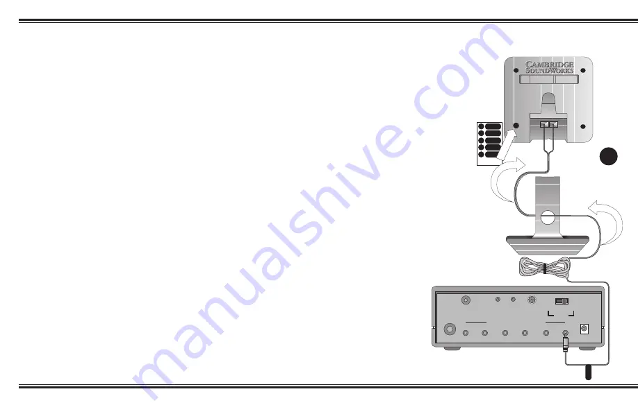
1. Identify a 3 meter cable.  Most

often, a satellite will be used with a
desktop stand.  In this case, thread
the bare wire end of a 3 meter cable
through the hole in the desktop
stand.  Connect this end to a
satellite (as shown in Diagram K).
Carefully insert the desktop stand’s
attachment arm into the socket in
the back of the satellite, taking up
any slack in the cable as required.

2. To use this satellite in the front left

position, remove the backing from
the small, round “L” label and
apply it to the back of the satellite
(see Diagram K).

3. Remove the backing from the

remaining, longer “L” label and wrap
it around the opposite end of the
speaker cable near the RCA-type plug.

4. Place the satellite in the front left

position.

5. Repeat this process using another 3

meter cable for the front right satellite,
using the “R” labels.

6. Connect another 3 meter cable to a

satellite.  Use the “C” (center) labels.
If used, the Monitor Stand attaches to
the satellite in the same  manner as the
Desktop Stands, although it does not
have a hole for the speaker wire.
Route the wire to the left or right side
of the attachment strut.  Position the
satellite.

7. If you wish to use the Floor Stands

with the rear satellites, assemble the
stand according to Attaching The
Floor Stand
 instructions on page 11.
Use the RS and LS labels (right and
left surround) and 5 meter cables.

8. Connect the subwoofer using the last 3

meter cable to the “SUB” labels.

   Diagram K: To connect the speaker
wire to each satellite, press one of the
spring-loaded tabs to expose the
connection hole.  Insert the bare end of
the wire into the exposed hole, then
release the tab to lock the wire in place.
Connect wires with red bands to red tab
connectors, and unmarked wires to
black tab connectors.
   Notes: Matching red wires to red
tabs and unmarked wires to black
tabs insures the speakers all play “in
phase”.  “Out-of-phase” connections
will do no electrical harm, but the
overall sound quality will be greatly
reduced.  You can substitute regular
18 gauge speaker wire to create
longer cables, if needed.

DOLBY DIGITAL
(AC-3) SPDIF IN

SPEAKER OUTPUTS

LINE IN REAR IN

C SUBWOOFER RS

LS

R

L

15V

DC IN

DIGITAL

DIN

ANALOG          AUTO

  INPUT

C

SUB

RS

LS

R

C

SUB

RS

LS

R

C

SUB

RS

LS

R

REAR

RIGHT

L

L

K

Содержание DTT250

Страница 1: ...ks of Cambridge SoundWorks Inc Newton MA The Creative logo and Sound Blaster logo are registered trademarks and the Environmental Audio logo and Creative Multi Speaker Surround are trademarks of Creat...

Страница 2: ...quipment is suitable for user installed application cards Modifications Any changes or modifications not expressly approved by the grantee of this device could void the user s authority to operate the...

Страница 3: ...than the other This plug will fit into the power outlet only one way This is a safety feature If you are unable to insert the plug fully into the outlet try reversing the plug If the plug should stil...

Страница 4: ...Speaker Placement 7 Speaker Wire and Stand Installation 10 Mounting The Speakers 11 Decoder Amplifier 12 Making Connections 12 Wiring Diagram 13 Connection to Sound Blaster 13 Decoder Amplifier Functi...

Страница 5: ...nd program material DeskTop Theater 5 1 DTT2500 Digital offers discreet four channel support for Microsoft DirectSound 3D and its other derivatives In some of today s best CD based action games DeskTo...

Страница 6: ...ger cables will be used on the surround channels but the satellites are otherwise identical If you need extra cable length for the front channel satellites use the pair with the longer cables instead...

Страница 7: ...KER TEST mode to position and balance the speakers 8 You may wish to experiment with speaker placement briefly before concealing the connecting cables and making the installation more permanent 9 The...

Страница 8: ...surround effects in Dolby Digital Dolby Surround and Creative Multi Speaker Surround modes They also provide the discreet rear sounds produced in four channel gaming 5 meters 16 feet of cable is provi...

Страница 9: ...inst the wall under the computer desk The nearer the subwoofer is to the corner of the room the stronger its maximum bass output will be We strongly recommend placing the subwoofer on the floor see Di...

Страница 10: ...R labels 6 Connect another 3 meter cable to a satellite Use the C center labels If used the Monitor Stand attaches to the satellite in the same manner as the Desktop Stands although it does not have...

Страница 11: ...L insuring a vibration free secure installation Leave about 3 8 of an inch of the screw head exposed to fit into the back of the speaker Plastic anchors may be needed to secure the screws into particu...

Страница 12: ...ut of your sound card and to the Line In minijack output of the Decoder Amplifier Connect the black stereo miniplugs to the Rear Out minijack output of your sound card if present and to the Rear In mi...

Страница 13: ...t on the decoder amplifier 3 Use the following procedure to configure the Sound Blaster Live sound card for four speakers Bring your mouse pointer to the top of the monitor screen to display the Creat...

Страница 14: ...to the right surround satellite left surround satellite and the subwoofer All of the indicator lights will blink on and off while the test sound generator is in operation The test sound will operate...

Страница 15: ...st sound can be clearly heard Finally adjust the front panel level controls for the center subwoofer and rear speakers Adjust each control so its speaker achieves a balanced output level with the left...

Страница 16: ...e these digitally transferred Dolby Surround programs through the digital Pro Logic decoder automatically When listening to DVD movies with 5 1 channel Dolby Digital sound be sure to listen only to th...

Страница 17: ...hannel games direct to each satellite channel It does not synthesize rear channel output so stereo signal in this mode will play just through the front two speakers and subwoofer The STEREO mode plays...

Страница 18: ...sable the Creative Multi Speaker Surround CMSS function by pressing the CMSS button until all four LEDs are off For movies with Dolby Digital 5 1 AC 3 soundtracks This signal is detected auto maticall...

Страница 19: ...500 Digital decoder amplifier unit 3 Select the MOVIE mode by pressing the Creative Multi Speaker Surround CMSS button until the LED for MOVIE mode lights up You can experience surround sound instead...

Страница 20: ...ra tion on your PC Otherwise select FourPoint under CMSS on your DTT2500 Digital decoder amplifier unit Playing Games Playing Multi format DVD Games These games have Dolby Digital or Dolby Pro Logic m...

Страница 21: ...2 Enable the Microphone source in the Mixer 3 Select one of the seven Karaoke modes under Environment in Creative Launcher 4 Press the AUDIO MODE button of the DTT2500 Digital decoder amplifier unit...

Страница 22: ...2500 Digital is intended for individual or small group listening and will achieve surprisingly high output levels However playing the system continuously at overly loud distorted levels on heavy bass...

Страница 23: ...353 1 8066964 Poland Freephone 00 800 353 1229 Hungary Freephone 06 800 1222 Russia Tel 353 1 8066967 Operating Hours Heures d ouverture ffnungszeiten Ore d ufficio Horario de oficina Openingstijden H...

Отзывы: