


Chapter 3: System planning
Data network planning
Data network planning
This section describes factors to be considered when planning PTP 650 data networks.
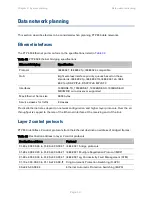
Ethernet interfaces
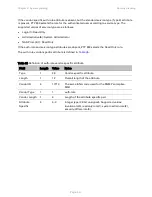
The PTP 650 Ethernet ports conform to the specifications listed in
Table 32 PTP 650 Ethernet bridging specifications
Ethernet Bridging
Specification
Protocol
IEEE802.1; IEEE802.1p; IEEE802.3 compatible
QoS
Eight wireless interface priority queues based on these
standards: IEEE 802.1p, IEEE 802.1Q, IEEE 802.1ah, IEEE
802.1ad, DSCP IPv4, DSCP IPv6, MPLS TC
Interfaces
100BASE-TX, 1000BASE-T, 1000BASE-SX, 1000BASE-LX
MDI/MDIX auto crossover supported
Max Ethernet frame size
9600 bytes
Service classes for traffic
8 classes
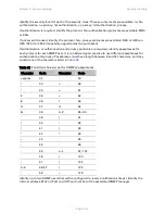
Practical Ethernet rates depend on network configuration and higher layer protocols. Over the air
throughput is capped to the rate of the Ethernet interface at the receiving end of the link.
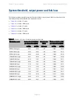
Layer 2 control protocols
PTP 650 identifies L2 control protocols from the Ethernet destination address of bridged frames:
Table 33 Destination address in layer 2 control protocols
Destination address
Protocol
01-80-c2-00-00-00 to 01-80-c2-00-00-0f IEEE 802.1 bridge protocols
01-80-c2-00-00-20 to 01-80-c2-00-00-2f IEEE 802.1 Multiple Registration Protocol (MRP)
01-80-c2-00-00-30 to 01-80-c2-00-00-3f IEEE 802.1ag, Connectivity Fault Management (CFM)
01-19-a7-00-00-00 to 01-19-a7-00-00-ff Ring Automatic Protection Switching (R-APS)
00-e0-2b-00-00-04
Ethernet Automatic Protection Switching (EAPS)
Page
3-27
Содержание PTP 650 Series
Страница 1: ...Cambium PTP 650 Series User Guide System Release 650 01 01 ...
Страница 88: ...Chapter 3 System planning Typical deployment Figure 24 Wall installation Page 3 3 ...
Страница 89: ...Chapter 3 System planning Typical deployment Figure 25 Roof installation Page 3 4 ...
Страница 91: ...Chapter 3 System planning Typical deployment Figure 27 ODU with optical SFP and PSU interfaces Page 3 6 ...
Страница 92: ...Chapter 3 System planning Typical deployment Figure 28 ODU with Aux and PSU interfaces Page 3 7 ...
Страница 264: ...Chapter 6 Configuration and alignment System menu Figure 69 QoS Configuration page IP MPLS Page 6 31 ...
Страница 289: ...Chapter 6 Configuration and alignment Management menu Figure 82 Time Configuration page SNTP enabled Page 6 56 ...


