background image

P

age

 1

8

P

age

 1

9

De-scale

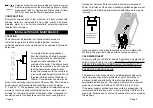
To gain access to internals of the water tank, the body lid must be 
removed. Remove the 4 screws, break the lid gasket seal and lift it 
clear of the body.

Note

: W

henever


the


body


lid


has


been


removed


from


the


boiler


a


new


lid


gasket


may


be


required


to


ensure


a


steam-tight


joint.

 D

amage


to


the


unit


caused


by


a


poor


lid


seal


is


not


covered


by


warranty.

S

cale


deposits


should


be


removed


from


all


internal


surfaces

particularly


the


heating


element

thermistor


and


level


sensors


by


gently


tapping


or


scraping.

 I

f


the


deposits


are


soft

use


a


nylon


pad


and


fl


ush


out.

 A

brasive


cleaning


materials


containing


scouring


powders


and


detergents


must


not


be


used

such


materials


can


cause


taste


problems.

S

uitable


chemical


de-scalants


must


only


be


used


in


accordance


with


the


manufacturer’s


recommendations.

 T

his


will


prevent


health


and


safety


issues

taste


problems


and


potential


damage


to


the


appliance.

 A

ll


trace


of


these


chemicals


must


be


removed


before


re-

commissioning


the


unit.

 M

isuse


of


such


chemicals


is


not


covered


by


the


product


warranty.

IMPORTANT Before re-commissioning the boiler it is 
important that all scale and moisture is removed from the 
level sensors and insulating gaskets, to avoid a false signal 
being transmitted through the scale to the boiler body. Failure 
to remove this scale and/or moisture will cause the sensor to 
indicate to the PCB that water is covering the element, whether 
or not water is present. In this situation the PCB will energise 
the element causing failure. If in doubt, protect the element by 
hand fi lling with water to the level of the draw-off tap before 
switching on the electrical supply to the boiler.

W

hen


the


red


service


indicator


light


on


the


front


of


the


boiler


is


illuminated

the


machine


has


been


starved


of


water


in


excess


of


2

minutes


and


the


solenoid


valve


has


been


disabled


to


prevent


damage


to


the


solenoid


coil


through


overheat.

 T

o


re-energise


the


solenoid

the


unit


must


be


disconnected


from


the


electrical


supply


and


then


switched


back


on

after


fi


rst


reinstating


the


water


supply.

I

f


the


unit


requires


servicing


the


red


service


indicator


will


fl


ash


a


sequence


of


light


pulses.

 A 

2x


or

 3

x-light


pulse


generally


indicates


that


the


low


or


normal


level


probes


require


de-scaling.

4x-light


pulse


means


the


water


level


has


reached


the


high


level


sensor


and


the


likelihood


is


that


the


normal


level


sensor


requires


de-scaling

or


the


machine


has


over-fi


lled


due


to


debris


trapped


in


the


solenoid


valve.

 T

he


debris


can


be


removed


by


drawing


plenty


of


water


from


the


dispense


tap

causing


the


solenoid


valve


to


operate


and


fl


ush


out


the


obstruction.

 T

he


machine


will


reset


itself


once


the


problem


has


cleared.

 I

f


this


does


not


rectify


the


problem

turn


off


the


water


supply


and


check


for


debris


in


the


solenoid


valve


fi


lter.


T

he


unit


can


be


used


normally


while


the


service


indicator


is


fl


ashing


a


4x


pulse.

 F

or


further


assistance

contact


our


service


department


on

 0113 

249


668

1  

e-mail


[email protected].


or


fi


nd


a


local


service


engineer


at


www.calomax.co.uk

Access to internal components can be gained by the removal 
of the outer casing lid and front panel. Once the outer casing 
is removed, access to the Service Area has been gained. This 
access must be restricted to persons having knowledge and 
practical experience of the appliance, in particular as far as safety 
and hygiene are concerned.

SERVICE INSTRUCTIONS

Содержание eclipse 3C10

Страница 1: ...HE ECLIPSE RANGE OF WATER BOILERS Please read these instructions carefully before operating your boiler for the first time Issue 2 026 07 10 DCR 810 Calomax Limited Lupton Avenue Leeds LS9 7DD Tel 011...

Страница 2: ...le engineer in your area visit our website www calomax co uk contact our service department on 0113 249 6681 or e mail service calomax co uk CHECK LIST counter top models Before commencing installatio...

Страница 3: ...C and 35 C The appliance is not suitable for installation where a water jet could be used Install the boiler on a surface or wall suitable for the working weight of the boiler Allow clearance for vent...

Страница 4: ...f the machine is operated without the overfill pipe being extended as advised any subsequent damage incurred will be the responsibility of the installer DIMENSIONS AND WEIGHTS 3C5 3C10 Height 570mm 57...

Страница 5: ...en should be supervised to ensure that they do not play with the appliance In the event of the power supply lead to the boiler becoming damaged the appliance must be removed from service A replacement...

Страница 6: ...t Replace Circuit Board Overboiling Excessive internal scale See De Scale page 19 Faulty wiring to thermistor faulty thermistor Temperature controller needs adjusting Element failed to earth Defective...

Страница 7: ...BODY TAP SLOTTED STEM DRAW OFF TAP BODY MODULAR HEAT SHIELD BLUE SLOW FILL NOZZLE MODULAR P C B TESTED MODULAR LIGHT PCB TESTED ELEMENT 3kW RESET KIT MODULER THERMISTOR ASSEMBLY KIT SOLENOID VALVE 1 2...

Страница 8: ...set of 8 seals 2 sizes Exploded parts view for Eclipse 3W5 To be read in conjunction with the spare parts list 17 1 2 4 3 7 8 5 13 20 18 If parts required are not identified please contact Calomax Lim...

Страница 9: ...lipse 3C5 3C10 To be read in conjunction with the spare parts list 11 12 14 19 Complete set of 8 seals 2 sizes 15 or 17 1 If parts required are not identified please contact Calomax Limited 2 4 3 6 20...

Страница 10: ...draw off tap before switching on the electrical supply to the boiler When the red service indicator light on the front of the boiler is illuminated the machine has been starved of water in excess of 2...

Страница 11: ...rature Set Point The temperature potentiometer Pot is pre set at Calomax and will only require adjustment in exceptional circumstances Contact Calomax for advice Water boils at different temperatures...

Страница 12: ...base warranty Some factors are beyond our control and would invalidate the warranty offered These include Incorrect installation High Low water pressure Incorrect voltage supply Accidental damage Lime...

Страница 13: ...113 235 0358 e mail service calomax co uk Model Serial Number Draw off Capacity 3C5 3C10 3W5 5 Litres 10 Litres 5 Litres Heat up Time First fill to full capacity 3C5 3C10 3W5 21 Minutes 34 Minutes 21...

Отзывы: