Lines
from
Tel.
Co.
(RJ21x
Block)
Telephone
Switch
(if present)
4 Outside Lines to Unit (modular or bare wire)
4 Lines to Telephone Switch
or Desktop Phones
4 Modular phone cords
carrying 1 line each
(RJ11) to unit Inputs
4 Modular phone cords
carrying 1 line each
(RJ11) from unit Outputs
Bare wire to
Modular Adapters
(if needed)
Deluxe Unit
(4 Line Model)
Out to
Desktop
Phones
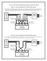
Lines coming into the building from the telephone company are connected to the input jacks on the monitoring unit. If
these lines do not terminate in modular connectors, solid wire to modular adapters need to be installed. The output lines
from the unit go to the desktop phones. If a telephone switch is present, they connect through the switch first.
Fig. G3a Series Connection for 2-Wire (RJ11) system
Lines
from
Tel.
Co.
(RJ21x
Block)
Telephone
Switch
(if present)
4 Outside Lines to Unit (modular or bare wire)
4 Lines to Telephone Switch
or Desktop Phones
2 Modular phone cords
carrying 2 lines each
(RJ14) to unit Inputs
2 Modular phone cords
carrying 2 lines each
(RJ14) from unit Outputs
Bare wire to
Modular Adapters
(if needed)
Port 2
L2
Port 4
L4
Deluxe Unit
(4 Line Model)
Out to
Desktop
Phones
Fig. G3b Series Connection for 4-Wire (RJ14) system
In a 4-wire (RJ14) system each phone cord carries 2 phone lines. Notice only 2 cords are connected to the inputs and of
the monitoring unit. These cords are connected to Ports 1 and 3. Ports 2 and 4 are not connected.
Port 3
L3/L4
In
Out
Port 1
L1/L2
In
Out
Port 1
L1
/L2
Port 3
L3
/L4
Port 2
L2
Port 4
L4
In
Out
In
Out
In
Out
In
Out
27
( Units set to Current Detection mode must be connected in Series )


