

Code 543513
Temperature safety relief valve. EC certified and approved to German DIN standards. Redundant safety sensor. Connections 3/4”
F. Chrome plated brass body. Stainless steel spring. EPDM seals. Temperature range 5 –110°C. Nominal set temperature 95°C.
Maximum working pressure 10 bar. Complete with 1/2” M remote probe with pocket. Length of capillary 1300 mm.
SPECIFICATION SUMMARIES
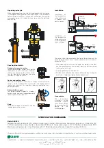
Operating principle
When the temperature rises, the fluid contained within the sensor
(1) undergoes a change of state from liquid to gas. The consequent
volume increase creates a mechanical movement causing the
expandable bellows (2), inside the valve, to push on the obturator
and lift it up.
Construction details
Redundant expansion system
The entire expansion system has a built-in
redundancy (1)-(2) to ensure maximum
safety, so if one part of the sensor system
fails the other part will perform the same
functions as the entire sensor.
Pocket and capillary tubes
The size of the pocket is such that it is always in contact with the
sensors, which improves heat transmission and keeps thermal
inertia to a minimum. The capillary tubes are protected by a
galvanized sheath.
Bellows holder support
The bellows holder support is made of
acetalic resin and can be repositioned by
loosening the knurled lock nut.
Drain
The lower part of the valve contains a button
in order to drain the system.
1
2
1
2
➩
We reserve the right to change our products and their relevant technical data, contained in this publication, at any time and without prior notice.
CALEFFI S.P.A.
· I ·
28010 FONTANETO D’AGOGNA (NO)
·
S.R. 229, N.25
·
TEL. +39 0322 8491 R.A.
·
FAX +39 0322 863723
·
www.caleffi.com
·
·
© Copyright 2007 Caleffi S.P.A.
CALEFFI
Installation
DOMESTIC
water supply
safety
discharge
mains
inlet
Hot
water
storage
safety
discharge
mains
inlet
The sensor should be mounted at the top of the boiler or on the
outlet piping upstream of any isolating device and at a maximum
distance of 0,5 m.
1. After mounting the valve on the pipe, according to the flow
direction indicated on the valve body, place the part connected
to the sensor in its seat.
2. Loosely tighten the knurled lock nut.
3. Position the sheath outlet that connects the probe by turning the
black cap. Completely tighten the knurled lock nut.
Installation of
the temperature
safety relief valve
in boilers with
built-in heater.
Installation of
the temperature
safety relief valve
in the emergency
heat exchanger.
Accessories
We recommend
inserting a visible
discharge tundish
(5521 series Caleffi)
when connecting the
device to the
discharge pipe.
1
2
3


