background image

22

PROCEDURE PARTICOLARI

Primo inserimento delle batterie nell’attuatore/ attuatore non ancora associato alla centralina

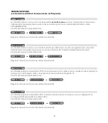
Dopo aver inserito le batterie per la prima volta, il LED dell’attuatore lampeggia per 2 volte. Il LED continuerà a lampeggiare 2 volte ogni 2 minuti per segnalare che non è stata ancora
eseguita l’associazione con la centralina. 

Verifica del livello di comunicazione tra attuatore e centralina

La centralina deve essere accesa e funzionante, l’attuatore deve essere correttamente associato alla centralina. Toccare contemporaneamente due tasti incrociati sull’attuatore, per 2
secondi (ad esempio quello in basso a sinistra e quello in alto a destra). Immediatamente dopo il rilascio è possibile verificare attraverso il LED di segnalazione:
- il LED lampeggia 4 volte il livello di comunicazione è OTTIMO
- il LED lampeggia 3 volte il livello di comunicazione è DISCRETO
- il LED lampeggia 2 volte il livello di comunicazione è SUFFICIENTE
- il LED si illumina per 2 secondi significa che l’attuatore non ha ricevuto alcun segnale dalla centralina. In tal caso valutare la necessità di installare un ripetitore di segnale.

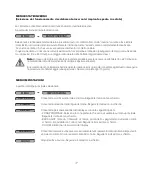
Apertura o chiusura manuale dell’attuatore

Selezionare sulla centralina: MENU-INSTALLAZIONE-GESTIONE ZONE-MODIFICA ZONA- [scegliere la zona corrispondente all’attuatore]-TEST-APERTO/CHIUSO.
Alla richiesta sul display, toccare contemporaneamente due tasti incrociati sull’attuatore, per 2 secondi. Immediatamente dopo il rilascio è possibile verificare attraverso il LED di
segnalazione:
- il LED si accende per 1 secondo, il comando non è stato ricevuto. L’attuatore non esegue nessuna operazione.
- il LED lampeggia ogni 0,5 secondi il comando è stato ricevuto; il LED rimane lampeggiante per tutto il periodo di azionamento del motore. L’attuatore esegue una apertura (o chiusura)
completa. Si consiglia di effettuare l’operazione con l’attuatore montato sulla valvola.

RESET ad impostazioni di fabbrica dell’attuatore

E’ possibile resettare l’attuatore alle condizioni di fabbrica. In tal caso viene persa irrimediabilmente l’associazione con la centralina. Si raccomanda di eseguire l’operazione solo in caso
di estrema necessità. Eseguita questa operazione occorrerà anche cancellare l’associazione attuatore-centralina tramite l’apposita funzione nel MENU INSTALLAZIONE, sulla centralina.
Toccare contemporaneamente i due tasti in basso sull’attuatore (ovvero quelli sotto la scritta Caleffi), per 2 secondi. Il LED attuatore lampeggerà per 4 secondi, durante i quali occorre
tenere premuti contemporaneamente i 2 tasti lato alto sull’attuatore. Il motore si porta nella posizione tutto aperto e viene cancellato il numero identificativo della centralina a cui era
associato. Il LED attuatore si illumina per 2 secondi. L’attuatore si porta quindi nello stato "batterie inserite, ma attuatore NON associato a nessuna centralina."

ANOMALIE

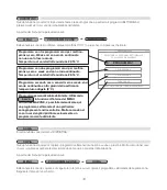
Nel caso di anomalie di funzionamento compare nella schermata principale un campo contenente l’icona

. Selezionata l’icona e premuto il tasto OK è possibile visualizzare, nelle

schermate successive, le anomalie presenti. La presenza di una anomalia è evidenziata anche nella schermata di stand by che normalmente è una schermata con indicazione dell’ora e
del logo Caleffi in colore bianco; nel caso di anomalia i caratteri diventano rossi.z

Batterie scariche - sostituzione

Se il livello della carica delle batterie di un attuatore è insufficiente
per la normale operatività, il problema viene segnalato tramite il simbolo

sul display

della centralina. Il LED dell’attuatore lampeggia tre volte ogni dieci minuti. L’attuatore si porta
automaticamente nella posizione di apertura=50%. 

La sostituzione delle batterie

non comporta la perdita dell’associazione con la centralina di
controllo.

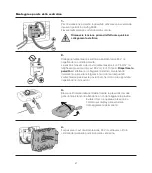
Per sostituire le batterie:

1) Estrarre il coperchio del comando spingendo il perno di blocco quadro con la punta di una
penna. Tirare il coperchio nella direzione della freccia.
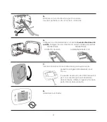
2) Inserire le due batterie tipo stilo AA 1,5 V 

rispettando la corretta polarità

. Il LED

sull’attuatore lampeggerà due volte per un secondo. Richiudere il coperchio.

Perdita di comunicazione tra attuatore (o altro dispositivo ad onde radio) e centralina.

Se l’attuatore perde la comunicazione con la centralina per più di 40 minuti, il problema viene segnalato sul display tramite il simbolo 

. Selezionando l’icona, il display

mostrerà l’informazione relativa a quale attuatore ha perso la comunicazione. Ad ogni attuatore viene assegnato una numerazione da 1 a 4 corrispondente all’ordine con il quale è stato
associato alla centralina. Per garantire comunque una regolazione della temperatura ambiente, l’attuatore regola con un set point fisso di 20°C utilizzando il suo sensore interno di
temperatura.  
Verificare che i dispositivi siano integri, che la portata del segnale radio sia sufficiente (vedere funzione di test), che le batterie degli attuatori siano cariche, che il sensore di temperatura
sia correttamente illuminato (e che quindi abbia un livello di carica sufficiente per la trasmissione del segnale).

Il display della centralina è spento

Verificare che la centralina sia alimentata elettricamente e che l’alimentatore sia collegato correttamente (corretta polarità). In caso questi controlli diano esito negativo contattare l’assistenza
tecnica Caleffi.

La temperatura della stanza è diversa dal setpoint impostato

Per effettuare l’osservazione occorre attendere un periodo di tempo ragionevole dalla impostazione del setpoint. Verificare che la caldaia funzioni regolarmente e che gli attuatori valvola
radiatore funzionino correttamente .Verificare che il valore di temperatura rilevata sia allineato con quella ambiente tramite la funzione “INFO”. Controllare che il sensore di temperatura
ambiente (se installato) sia opportunamente posizionato e non esposto alla luce diretta (falsando il valore di temperatura rilevato). Se non presente valutare l’inserimento del sensore di
temperatura ambiente. In caso questi controlli diano esito negativo contattare l’assistenza tecnica Caleffi.

Содержание 210510

Страница 1: ...mperaturregelsystem f r Heizk rper D Syst me lectronique de r gulation thermique pour radiateurs F Copyright 2014 Caleffi www caleffi com 28238 MANUALE DI INSTALLAZIONE E MESSA IN SERVIZIO INSTALLATIO...

Страница 2: ...parametri impostati di temperatura e dei cicli di comfort od attenuazione la centralina invia il segnale di apertura o chiusura modulante agli attuatori ed accensione spegnimento caldaia La gestione d...

Страница 3: ...dell impianto 1 ATTENZIONE Rischio di shock elettrico Parti in tensione Togliere l alimentazione elettrica prima di aprire la scatola del dispositivo 2 I cablaggi devono essere effettuati a regola d a...

Страница 4: ...ore Mantenimento dati di impostazione senza alimentazione indefinito Alimentatore cod 210004 per centralina di regolazione cod 210100 Alimentazione 230 V ac Tensione in uscita 24 V dc Corrente in usci...

Страница 5: ...IVO FINO ALLE 14 00 DEL ALLARME INFORMAZIONI DI STATO GIORNO DATA ORA RICHIESTA DI CALORE ATTIVATA ELENCO ZONE MENU PRINCIPALE TEMPERATURA RILEVATA NELLA ZONA TASTO INDIETRO TASTO SCORRIMENTO GI SCELT...

Страница 6: ...re lo stesso modo di funzionamento per tutte le zone seguire le indicazioni nel capitolo MENU MODO ZONE Attivazione temporanea della modalit comfort della singola zona forzatura del set point Selezion...

Страница 7: ...indirette di riscaldamento possibilmente ad una altezza da terra compresa fra 1 2 m 1 5 m La distanza massima di trasmissione in ambienti chiusi privi di ostacoli particolari come muri spessi in ceme...

Страница 8: ...ici per evitare il furto danneggiamento Avvitare l apposita vite nel foro di blocco Nota L attuatore viene impostato di fabbrica nella posizione di completa apertura della valvola per facilitare l ins...

Страница 9: ...ezza massima dei cavi 24 V dc di 10 metri Rispettare la polarit ed effettuare i collegamenti elettrici mantenendo l isolamento per evitare folgorazioni o danni al dispositivo L alimentatore pu essere...

Страница 10: ...nettore di comando caldaia se presente CONNETTORE CONNETTORE CONTATTO CALDAIA ALIMENTAZIONE 24 V dc 7 Inserire il frontale facendo combaciare la parte superiore del pannello e spingere delicatamente f...

Страница 11: ...nferma per proseguire La stessa procedura va ripetuta per minuti e la data 24 04 2014 28 ORA E DATA 00 IMPOSTA ORA E DATA 00 IMPOST A T TA A ORA E DA AT MPOST TA ORA E DA A T TA ORA E DA AT 28 24 04 2...

Страница 12: ...edendo all apposito menu di modifica testo Premendo su AVANTI si prosegue nell installazione AVANTI CAMERA SALOTTO CAMERA 2 BAGNO BAGNO 2 CUCINA INGRESSO SALA PRANZO SALOTTO SELEZIONA PER MODIFICARE I...

Страница 13: ...ERNO IMPOSTAZIONI MODO ZONE INSTALLAZIONE 24 04 14 GIO INST 14 48 MENU PROGRAMMA ZONE TE INVERNO A ATE INVERNO EST TA AZIONI IMPOST TAZIONI ALLAZIONE NST TALLAZIONE MODO ZONE SELEZIONA OPZIONE SELEZIO...

Страница 14: ...IONA OPZIONE 6 Selezionare la zona da configurare INSTALLA SELEZIONA LA ZONA DA CONFERMARE GIO 24 04 14 14 48 CAMERA SALOTTO BAGNO CAMERA 2 CUCINA BAGNO 2 SALA PRANZO INGRESSO 24 04 14 GIO CAMERA SALO...

Страница 15: ...lizzato un segnale di allarme In tal caso ripetere la procedura o consultare la sezione errori allarmi SALOTTO PREMI UN TASTO QUALUNQUE GIO 24 04 14 14 48 HAI AGGIORNATO CON SUCCESSO IL SENSORE DI TEM...

Страница 16: ...ATTUATORE PER 2 SECONDI ENTRO 2 MINUTI 3 Scegliere il tipo di radiatore sul quale stato montato l attuatore al fine di migliorare la regolazione climatica TIPO RAD SELEZIONA OPZIONE GIO 24 04 14 14 48...

Страница 17: ...le indicazioni a schermo per attivare l impostazione La centralina spegne il riscaldamento OFF fino all ora e data di ritorno dalla vacanza chiudendo tutte le valvole e la caldaia in caso sia collega...

Страница 18: ...e le indicazioni a schermo DISPLAY Consente la personalizzazione del display secondo le seguenti opzioni ZONA PRINCIPALE Seleziona la zona preferita che verr visualizzata sul menu principale Seguire l...

Страница 19: ...per eseguire l operazione MODIFICA Consente di modificare i valori relativi a una fascia oraria esistente con ora inizio ora fine e set point temperatura di regolazione Seguire le indicazioni a scher...

Страница 20: ...MENU PROGRAMMA ZONE COPIA SALVA RIPRISTINA MENU RIPRISTINA RIPRISTINA MATTINA PRANZO SERA WEEK END GIO 24 04 14 14 48 SELEZIONA LA PROGRAM SETTIMANALE TRA QUELLE DISPONIBILI Programma con tre program...

Страница 21: ...un luogo dove non rileva correttamente la temperatura ad esempio posizionamento non a una altezza da terra compresa fra 1 2 m 1 5 m o vicino a una sorgente di calore Consente di aggiungere un pulsant...

Страница 22: ...MIO VACANZA SPENTO MODIFICA RIPRISTINA SALVA COPIA INVERNO ESTATE ORAEDATA LINGUA DISPLAY SCENARIO SUONO Selezionaopzioni Sceglizonaogiorno Sceglizona Sceglizona Sceglizona Cambiaoraedata Sceglilingua...

Страница 23: ...nella schermata principale un campo contenente l icona Selezionata l icona e premuto il tasto OK possibile visualizzare nelle schermate successive le anomalie presenti La presenza di una anomalia evi...

Страница 24: ...loro posizione si consiglia di utilizzare questo spazio dove inserire lo schema di installazione Questo consentir di facilitare alcune operazioni come l individuazione degli attuatori con batterie sca...

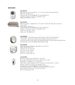
Страница 25: ...ttivare il funzionamento per tutte le zone in Automatico risparmio OFF senza dover agire direttamente sulla centralina di regolazione Comunicazione radio RF 868MHz Standard EnOcean Cod 210004 Alimenta...

Страница 26: ...ads Depending on the temperature parameters set and the comfort or set back cycles the controller sends a modulating opening or closing signal to the actuators and turns the boiler on and off The actu...

Страница 27: ...e and or system 1 CAUTION Risk of electric shock Live parts Cut off the electric supply before opening the device box 2 Wiring must be made according to the state of the art and in case of connection...

Страница 28: ...s Setting data storage without electric supply indefinitely Power supply code 210004 for thermal controller code 210100 Electric supply 230 V ac Output voltage 24 V dc Output current 180 mA Output pow...

Страница 29: ...CHEN MODE 20 0 C 23 9 C COMFORT MODE ON UNTIL 14 00 ALARM STATUS INFORMATION DAY DATE TIME HEAT REQUEST ACTIVATED ZONE LIST MAIN MENU MEASURED TEMPERATURE IN ZONE BACK button SCROLL DOWN button ZONE O...

Страница 30: ...on 8 C remains active To activate the same operating mode for all the zones follow the instructions given in the section ZONE MODE MENU Temporarily activating comfort mode of the individual zone forci...

Страница 31: ...heating sources possibly at a height between 1 2 1 5 metres from the ground The maximum transmission distance in closed environments without any particular obstacles such as thick reinforced concrete...

Страница 32: ...ed hole Note The actuator is factory set in the position with fully open valve to facilitate installation The motor is not started when the batteries are tted the actuator starts regulating only after...

Страница 33: ...of the 24 V dc cables is 10 metres Respect the polarity and make the electrical connections keeping the insulation in order to prevent electrocution or damage to the device The power supply can be po...

Страница 34: ...ables to the boiler command connector if present BOILER CONTAC ELECTRIC SUPPLY CONNECTOR CONNECTOR 24 V dc 7 Refit the front panel lining up the top of the front and rear panels and gently push it unt...

Страница 35: ...and DOWN buttons and press the con rmation button to continue Repeat the same procedure for the minutes and the date 24 04 2014 28 TIME DATE 00 ENTER TIME AND DATE 00 TE AT TIME AND D ENTER TE A ATE T...

Страница 36: ...nge the name of the zones as you wish by selecting the zone and accessing the dedicated text editing menu Press NEXT to continue with the installation GO AHEAD BEDROOM LIVING ROOM BEDROOM 2 BATHROOM B...

Страница 37: ...14 48 ZONE PROGRAM SUMMER WINTER SETTINGS ZONE MODE INSTALLATION 24 04 14 THU 14 48 MENU ZONE PROGRAM SUMMER WINTER SETTINGS TION ALLA ATION INST TALLA ZONE MODE SELECT OPTION 3 Hold down the con rma...

Страница 38: ...be con gured INSTALL SELECT THE ZONE TO BE CONFIRMED THU 24 04 14 14 48 BEDROOM LIVING ROOM BATHROOM BEDROOM 2 KITCHEN BATHROOM 2 DINING ROOM HALL 24 04 14 THU BEDROOM LIVING ROOM BEDROOM 2 THROO BA A...

Страница 39: ...ed In this case repeat the procedure or consult the section ERRORS ALARMS LIVING ROOM PRESS ANY BUTTON THU 24 04 14 14 48 YOU HAVE SUCCESSFULLY BOUND THE TEMPERATURE SENSOR IN THE ZONE LIVING ROOM SEN...

Страница 40: ...UTTON OF THE ACTUATOR FOR 2 SECONDS WITHIN 2 MINUTES 3 Select the type of radiator on which the actuator was installed in order to improve temperature regulation RADIATOR SELECT OPTION THU 24 04 14 14...

Страница 41: ...ect ECO Follow the on screen instructions to activate the setting The controller turns the heating off closing all the valves and the boiler if connected until the time and date of return from holiday...

Страница 42: ...the on screen instructions DISPLAY Allows customising the display with the following options MAIN ZONE To select your favourite zone that will be shown in the main menu Follow the on screen instructio...

Страница 43: ...gulation temperature A maximum of four time periods can be set Follow the on screen instructions MODIFY Allows modifying the values relating to an existing time period with start end time and setpoint...

Страница 44: ...NE PROGRAM COPY MENU ZONE PROGRAM COPY SAVE RESTORE MENU RESTORE RESTORE MORNING LUNCH EVENING WEEKEND THU 24 04 14 14 48 SELECT WEEKLY PROGRAM FROM THOSE AVAILABLE Program with three timetables for m...

Страница 45: ...e the temperature e g it is not positioned at a height between 1 2 and 1 5 metres from the ground or close to a heat source Allows adding a click switch optional Follow the on screen instructions Acti...

Страница 46: ...AY OFF MODIFY RESTORE SAVE COPY WINTER SUMMER TIME DATE LANGUAGE DISPLAY SCENARIO SOUND Selectoptions Selectzoneorday Selectzone Selectzone Selectzone Changetimeanddate Selectlanguage SAVE SELECT ON O...

Страница 47: ...ults the icon appears on the main menu screen Selecting the icon and pressing OK it is possible to visualize current faults in the next screens A fault is put into evidence also by the stand by screen...

Страница 48: ...ify the actuators and their position it is advisable to use this space for the installation diagram This will make some operations easier such as identifying actuators with at batteries an identi cati...

Страница 49: ...ch The three buttons allow activating AuTO ECO OFF operating mode without having to act directly on the thermal controller Radio communication RF 868 MHz Standard EnOcean Code 210004 Power supply for...

Страница 50: ...rten Sensoren erfasst Je nach eingestellten Temperaturparametern und Komfort oder D mpfungszyklen sendet die Steuerzentrale ein modulierendes Signal zum ffnen oder Schlie en an die Thermostatventile u...

Страница 51: ...intr chtigen 1 ACHTUNG Stromschlaggefahr Unter Spannung stehende Teile Vor Eingriffen jeder Art muss die Stromversorgung unterbrochen werden 2 Die elektrischen Anschl sse m ssen fachgerecht nach den V...

Страница 52: ...2 Std Beibehaltung der eingestellten Daten ohne Versorgungsspannung unendlich Speiseger t Code 210004 f r Steuerzentrale Code 210100 Versorgungsspannung 230 V ac Ausgangsspannung 24 V dc Ausgangsstrom...

Страница 53: ...C 23 9 C KOMFORT MODUS BIS 14 00 AM ALARM STATUSINFORMATIONEN TAG DATUM UHRZEIT AKTIVIERTE HEIZANFORDERUNG LISTE DER ZONEN HAUPTMEN IN DER ZONE ERFASSTE TEMPERATUR TASTE ZUR CK TASTE ABFW RTS AUSWAHL...

Страница 54: ...e Frostschutztemperatur 8 C bleibt in jedem Fall aktiviert Um den gleichen Betriebsmodus f r alle Zonen zu aktivieren die Angaben im Kapitel MEN ZONENMODUS befolgen Vor bergehende Aktivierung des Komf...

Страница 55: ...ntrale fern von T ren Fenstern Heizk rpern und indirekten W rmequellen sowie m glichst in einer H he zwischen 1 2 m 1 5 m installieren Die maximale bertragungsreichweite in geschlossenen R umen ohne b...

Страница 56: ...tatventil wird werkseitig auf die komplett ge ffnete Ventilposition eingestellt um die Installation zu vereinfachen Nach dem Einsetzen der Batterien wird der Motor nicht gestartet Erst nach der Verbin...

Страница 57: ...V dc Kabel bel uft sich auf 10 m Auf die korrekte Polarit t achten und die elektrischen Anschl sse unter Beibehaltung der Isolierung vornehmen um Stromschl ge oder Sch den an der Vorrichtung zu vermei...

Страница 58: ...s Kessels sofern vorhanden anschlie en STECKVERBINDER STECKVERBINDER KONTAKT ZU KESSEL 24 V dc VERSORGUNG 7 Die Frontblende einsetzen hierzu die Oberseite der Abdeckung korrekt anf gen und leicht dr c...

Страница 59: ...ern und die Taste Best tigen dr cken um fortzufahren Das gleiche Verfahren gilt f r die Einstellung von Minuten und Datum 24 04 2014 28 UHR 00 UHRZEIT UND DATUM EINSTELLEN 00 UHRZEIT UND D TUM EINSTEL...

Страница 60: ...derung nach Bedarf ge ndert werden Nach Dr cken von VORW RTS wird mit der Installation fortgefahren VORW RTS KAMMER WOHNBEREICH ZIMMER 2 BADEZIMMER BADEZIMMER 2 K CHE EINGANGSBEREICH ESSZIMMER WOHNBER...

Страница 61: ...LEN DO 24 04 14 14 48 ZONENPROGRAMM SOMMER WINTER EINSTELLUNGEN ZONENMODUS INSTALLATION 24 04 14 O D 14 48 MEN MM A OGR ONENPR Z WINTER SOMMER UNGEN EINSTELL TION ALLA ATION INST TALLA ONENMODUS Z OPT...

Страница 62: ...HLEN 6 Die zu kon gurierende Zone ausw hlen INSTALLIEREN DIE ZU BEST TIGENDE ZONE W HLEN DO 24 04 14 14 48 KAMMER WOHNBEREICH BADEZIMMER ZIMMER 2 K CHE BADEZIMMER 2 ESSZIMMER EINGANGSBEREICH 24 04 14...

Страница 63: ...Alarmsignal In diesem Fall den Vorgang wiederholen oder im Abschnitt Fehler Alarme nachlesen WOHNBEREICH EINE BELIEBIGE TASTE DR CKEN DO 24 04 14 14 48 DER TEMPERATURSENSOR IN DER FOLGENDEN ZONE WURDE...

Страница 64: ...hlen an dem das Thermostatventil installiert ist um die Temperatureinstellung zu optimieren RADIATOR OPTION AUSW HLEN DO 24 04 14 14 48 ALUMINIUM GUSSEISEN STAHL 0 24 04 14 DO D GUSSEISEN ST 14 48 OR...

Страница 65: ...Einstellung zu aktivieren Die Steuerzentrale schaltet die Heizung bis zur uhrzeit und zum Datum der R ckkehr aus den Ferien aus OFF und schlie t alle Ventile und den Kessel sofern angeschlossen Die Fr...

Страница 66: ...ben auf dem Bildschirm folgen ANZEIGE Erm glicht die individuelle Einstellung des Displays mit den folgenden Optionen HAuPTZONE W hlt die gew nschte Zone aus die im Hauptmen angezeigt wird Den Angaben...

Страница 67: ...ldschirm folgen um den Vorgang durchzuf hren NDERN Erm glicht es die Werte einer vorhandenen Zeitspanne mit Beginn und Ende sowie den Sollwert Regeltemperatur einzustellen Den Angaben auf dem Bildschi...

Страница 68: ...ROGRAMM KOPIEREN SPEICHERN WIEDERHERSTELLEN MEN WIEDERHERSTELLEN WIEDERHERSTELLEN MORGEN MITTAG ABEND WOCHENENDE DO 24 04 14 14 48 DAS WOCHENPROGRAMM UNTER DEN VERF GBAREN PROGRAMMEN W HLEN Programm m...

Страница 69: ...wo sie die Temperatur nicht korrekt erfasst wenn sie z B nicht in einer H he von 1 2 m bis 1 5 m montiert ist oder wenn sie sich nahe einer W rmequelle be ndet Erm glicht es eine Klick Taste optional...

Страница 70: ...FERIEN HEIZUNGAUS NDERN WIEDERHERSTELLEN SPEICHERN KOPIEREN WINTER SOMMER UHR SPRACHE ANZEIGE SZENARIO TON Optionenausw hlen ZoneoderTagw hlen Zonew hlen Zonew hlen Zonew hlen UhrzeitundDatum ndern Sp...

Страница 71: ...Symbols und Dr cken der Taste OK k nnen auf den nachfolgenden Bildschirmen die vorhandenen St rungen angezeigt werden Auf das Vorhandensein einer St rung wird auch auf dem Standby Bildschirm hingewies...

Страница 72: ...n problemlos zu identi zieren wird empfohlen an dieser Stelle das Installationsschema einzuf gen Dies vereinfacht bestimmte Vorg nge wie z B das Aus ndigmachen der Thermostatventile mit leerer Batteri...

Страница 73: ...rei Tasten kann die Funktionsweise Automatisch Sparen OFF aktiviert werden ohne hierzu direkt an der Steuerzentrale eingreifen zu m ssen Funkkommunikation RF 868MHz Standard EnOcean Code 210004 Speise...

Страница 74: ...ycles de confort ou de r duit le r gulateur transmet le signal d ouverture ou de fermeture modulante aux commandes lectroniques et d allumage extinction la chaudi re La gestion des commandes lectroniq...

Страница 75: ...rrait compromettre le fonctionnement du dispositif et ou de l installation 1 ATTENTION Risque d lectrocution Parties sous tension Couper l alimentation lectrique avant d ouvrir le bo tier du dispositi...

Страница 76: ...2 heures Maintien des donn es de configuration sans alimentation ind fini Alimentateur r f 210004 pour r gulateur thermique r f 210100 Alimentation 230 V ca Tension en sortie 24 V cc Courant en sortie...

Страница 77: ...U ALARME INFORMATIONS D TAT JOUR DATE HEURE DEMANDE DE CHAUFFAGE ACTIV E LISTE DES ZONES MENU PRINCIPAL TEMP RATURE RELEV E DANS LA ZONE TOUCHE PR C DENT TOUCHE DE D FILEMENT VERS LE BAS CHOIX MODE DE...

Страница 78: ...Pour activer le m me mode de fonctionnement pour toutes les zones suivez les instructions du chapitre MENU MODE ZONES Activation temporaire du mode confort d une zone for age du point de consigne S l...

Страница 79: ...le si possible une hauteur du sol comprise entre 1 2 m et 1 5 m La distance maximale de transmission dans des pi ces ferm es d pourvues d obstacles particuliers tels que des murs pais en b ton arm por...

Страница 80: ...est r gl e l usine sur la position d ouverture totale du robinet pour en faciliter l installation La mise en place des piles ne met pas le moteur en marche la commande lectronique ne commencera r gule...

Страница 81: ...st 10 m tres Respectez la polarit et r alisez les branchements lectriques en veillant maintenir l isolement afin d viter tout risque d lectrocution ou d endommagement du dispositif L alimentateur peut...

Страница 82: ...la chaudi re si pr sent CONNECTEUR CONNECTEUR CONTACT CHAUDI RE ALIMENTATION 24 V cc 7 Ins rez la face avant en faisant co ncider parfaitement la partie sup rieure du panneau et poussez d licatement j...

Страница 83: ...ontinuer R p tez la m me proc dure pour les minutes et la date 24 04 2014 28 HEURE ET DATE 00 PROGRAMMER HEURE ET DATE 00 OGR PR TE A T D MMER HEURE E A OGR TE A ATE T D HEURE E 28 24 04 2014 4 Sp cif...

Страница 84: ...sp ci que de modi cation de texte Appuyez sur SUIVANT pour continuer l installation SUIVANT CHAMBRE SALON CHAMBRE 2 SALLE DE BAINS SALLE DE BAINS 2 CUISINE ENTR E SALLE MANGER SALON S LECTIONNER POUR...

Страница 85: ...NSTALLATION 24 04 14 J 14 48 MENU PROGRAMME ZONE T HIVER TIONS CONFIGURA ATIONS TION ALLA ATION INST TALLA MODE ZONE S LECTIONNER OPTION S LECTIONNER OPTION 3 Maintenez enfonc e la touche de con rmati...

Страница 86: ...ctionnez la zone con gurer INSTALLER S LECTIONNER LA ZONE CONFIRMER J 24 04 14 14 48 CHAMBRE SALON SALLE DE BAINS CHAMBRE 2 CUISINE SALLE DE BAINS 2 SALLE MANGER ENTR E 24 04 14 J CHAMBRE SALON CHAMBR...

Страница 87: ...Si l accouplement a chou un signal d alarme s af che Dans ce cas r p tez la proc dure ou consultez la section erreurs alarmes SALON APPUYER SUR UNE TOUCHE J 24 04 14 14 48 LA MISE JOUR DU CAPTEUR DE T...

Страница 88: ...NDES DANS LES 2 MINUTES SUIVANTES 3 Choisissez le type de radiateur sur lequel la commande lectronique a t mont e a n d am liorer la r gulation climatique TYPE RAD S LECTIONNER OPTION J 24 04 14 14 48...

Страница 89: ...vez les instructions qui s af chent pour activer la programmation Le r gulateur teint le chauffage OFF jusqu l heure et la date de retour des vacances en fermant tous les robinets et la chaudi re si e...

Страница 90: ...EUR Cette fonction permet de personnaliser l af cheur selon les options suivantes ZONE PRINCIPALE S lection de la zone pr f r e qui sera af ch e dans le menu principal Suivez les instructions qui s af...

Страница 91: ...on MODIFIER Cette fonction permet de modi er les valeurs relatives une plage horaire existante avec heure de d but heure de n et le point de consigne temp rature de r gulation Suivez les instructions...

Страница 92: ...af chent l cran PROGRAMME ZONE COPIER MENU PROGRAMME ZONE COPIER SAUVEGARDER R TABLIR MENU R TABLIR R TABLIR MATIN MIDI SOIR WEEKEND J 24 04 14 14 48 S LECTIONNER LA PROGRAMMATION HEBDOMADAIRE PARMI...

Страница 93: ...est install dans un endroit o il ne peut relever correctement la temp rature par exemple montage une hauteur du sol non comprise entre 1 2 m et 1 5 m o pr s d une source de chaleur Cette fonction perm...

Страница 94: ...ERGIE VACANCES TEINT MODIFIER R TABLIR SAUVEGARDER COPIER HIVER T HEUREETDATE LANGUE AFFICHEUR SC NARIO SON S lectionneroptions Choisirzoneoujour Choisirzone Choisirzone Choisirzone Changerheureetdate...

Страница 95: ...ento compare nella schermata principale un campo En cas d anomalies de fonctionnement la page cran principale affiche un champ contenant l ic ne En s lectionnant l ic ne et en appuyant sur la touche O...

Страница 96: ...r position il est recommand d utiliser cet espace pour tracer le sch ma d installation Cela facilitera certaines op rations comme par exemple la localisation des commandes lectroniques dont les piles...

Страница 97: ...permettent d activer le fonctionnement en Automatique conomie d nergie OFF sans besoin d agir directement sur le r gulateur thermique Communication radio RF 868MHz Standard EnOcean R f 210004 Alimenta...

Отзывы: