11
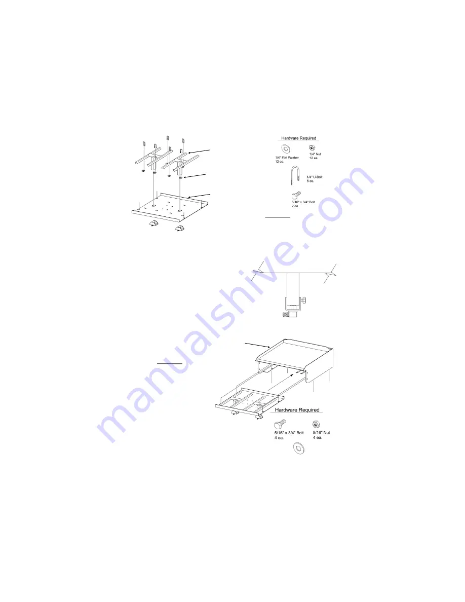
Step 4
Note: This step is completed
at the factory. It is only
shown to illustrate how to
complete the unit assembly.
1) Slide Burner Tray into
the Griddle Body as
Shown.
2) Secure the tray using
5/16” x 3/4” bolts (4 ea.),
5/16” Flat Washers (8 ea.) and 5/16” nuts (4
ea.). The Flat Washers should be under
the Griddle Body. Tighten the nuts and
bolts securely.
Step 3
Note: This step is completed at the factory.
It is only shown to illustrate how to complete
the unit assembly.
1) Slide Burner Tube Verticals through the square hole cut into the base
plate and rest burner tubes onto the Burner Brackets. Place U-Bolts
(6 ea.) over the Burner Tubes and
through the holes in the base plate
and secure with 1/4” Flat Washers
(12 ea.) and 1/4” Nuts (12 ea.).
Tighten U Bolt until they are snug
and secure.
2) Slide Jet Assembly on to the Burner
Vertical Tube and set air adjustment
so that the Jet is level with the
bottom of the Vertical Tube. Tighten
5/16” x 3/4” Bolt (2 ea.) to secure Jet
Assembly into place. (See figure B)
Griddle Head Weldment
Burner
Burner Base Plate
Burner Brackets
Figure B
5/16” Large Washers
8 ea.


