background image

UHF

E.  

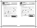
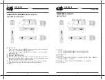
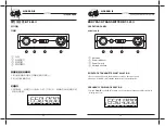
灵敏度调节菜单:

F.  

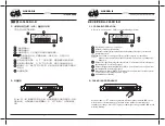
系统锁定功能菜单:

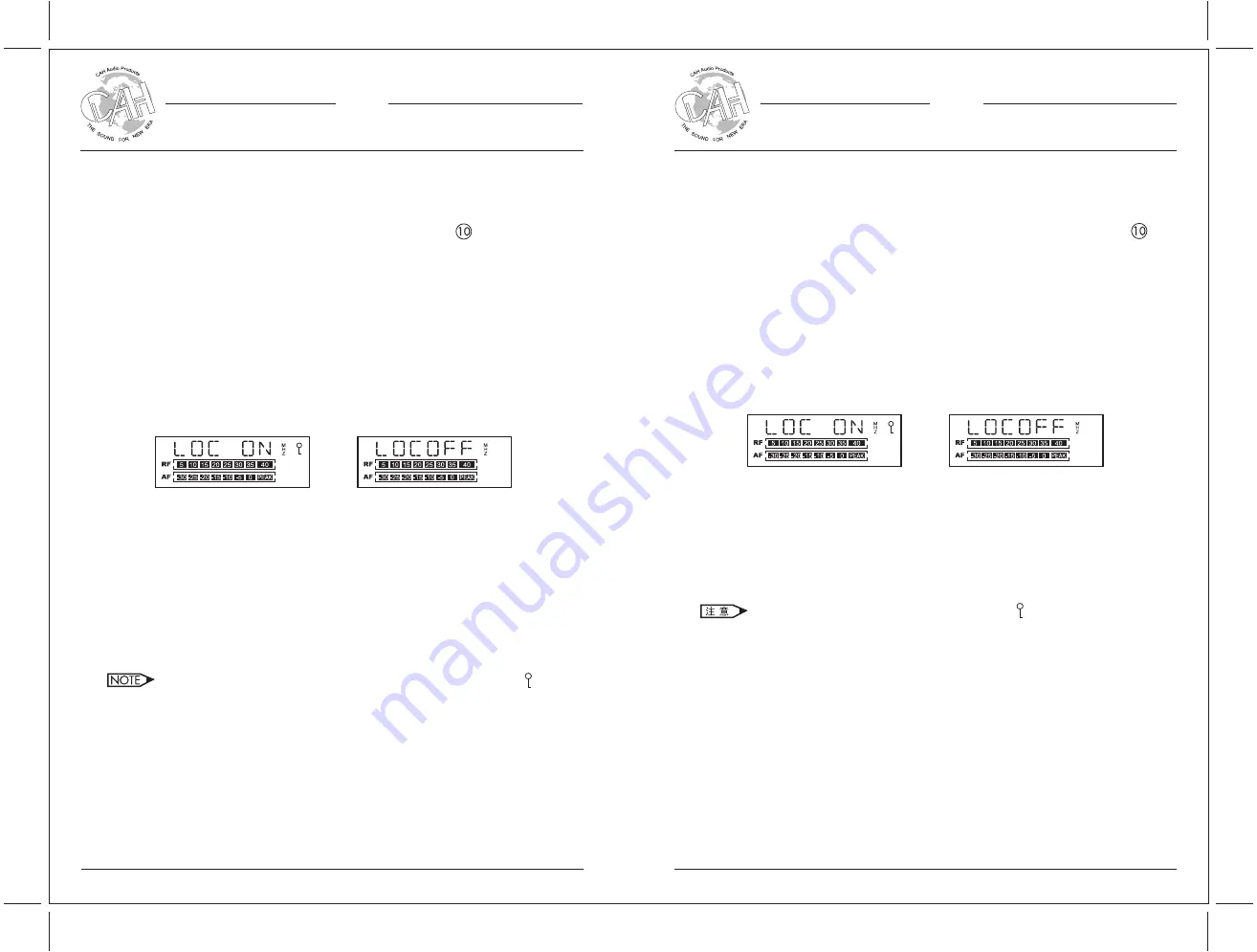
锁定和非锁定的系统状态如下图:

在背面板的 SQL-A、SQL-B 灵敏度调节旋钮 (见本操作手册第5页背面板图      ) 分

别用来调节A、B讯道的灵敏度。把调节旋钮向“MAX”顺时针方向扭动, 则灵敏度

较高, 接收距离也较远. 反之, 向“MIN”逆时针方向扭动, 则灵敏度较低, 接收距离

也较近。

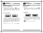
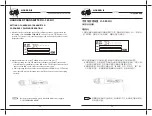
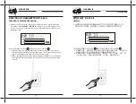
按“SET”键三次,屏幕显示“LOCK”,1 

~

 2 秒后屏幕会显示“LOC ON”

锁定状态)或“LOCOFF”(非锁定状态)如上图(“LOC ON”表示系统被

锁定,若为锁定状态,则不能改变当前的各种已设定的工作状态;若非锁定状

态,则可对所有菜单功能进行改变)。按“▲”切换到“LOC ON”锁定系统

当前设置;按“▼”切换到“LOCOFF”使系统可调节工作状态。最后再按

“SET” 键确认选择。

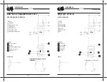
E.  SENSITIVITY ADJUSTMENT MENU:

F.  SYSTEM LOCKING MENU:

System locking and unlocking modes are shown as below:

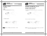
If the system is locked, the lock indicator will be displaying “    ”.

Pressing the “SET” button 3 times, the LCD screen will displays “LOCK”.  After 1 ~ 2 

seconds, LCD screen will display “LOC ON” or “LOCOFF” as shown above (“LOC ON” 

means that system is locked). When system is on a “LOC ON” mode, all system 

settings will be locked on the current settings and other further adjustment will be 

blocked.  Only when the system is on a “LOCOFF” mode (“LOCOFF” means system 

is unlocked that adjustments to the system settings are allowed).  You can press 

” button to switch the current system settings to a “LOC ON” mode or press the 

” button to switch the system to a “LOCOFF” mode.  Press “SET” again to 

confirm your setting.

Knobs SQL-A and SQL-B at the rear panel of the receiver (see       on the rear panel 

in Page 5) can be used to adjust the receiving signals of Channels A & B between 

the transmitters and receiver respectively.  By turning the knobs towards "MAX" 

clockwise, the sensitivity level for receiving signal from a longer distance will 

increase. By turning the knobs backwards counterclockwise to "MIN", the contrary 

will apply.

Professional Wireless Microphone System

UHF

U-3650D II

UHF 

专业无线话筒系统

U-3650D II

接收机 

U-3650D II-R 

RECEIVER U-3650D II-R 

8

8

若系统处于锁定状态,会出现锁定指示“    ”。

Содержание U-3650D II

Страница 1: ...U 3650D II U 3650D II U H F...

Страница 2: ...should be operated only from the type of power source indicated on the marking label LIGHTNING For added protection for this product during a lighting storm or when it is left unattended and unused f...

Страница 3: ...6 14 15 15 15 16 17 18 U 3650D II U 3650D II CAH PROFESSIONAL SOUND CO LTD Unit E F 21 F Luk Hop Industrial Building 8 Luk Hop Street San Po Kong Kln Hong Kong Tel 852 2766 3818 Fax 852 2363 0363 Webs...

Страница 4: ...ters 4 CPU control CPU controlled antenna diversity circuitry for increased RF gain improved reception and exceptional freedom from dropouts 5 LCD Liquid Crystal Display screen 6 System features with...

Страница 5: ...A Front Panel Rear Panel LCD Headphone Jack Power On Off Switch Volume Control LCD Screen Up and Down Buttons for frequency selection or other menu settings SET Button IR Port Antenna Sockets A B Pow...

Страница 6: ...ct the audio output for balanced connection or for unbalanced connection to a mixer or karaoke amplifier 5 Turn the volume control to minimum then press and hold the power switch for 1 2 seconds until...

Страница 7: ...B Signal Receiving Indicator When II is shown as above this means that Antenna B is receiving a signal Mute Indicator When MUTE is shown as above this means that the system is currently not receiving...

Страница 8: ...s on a LOCOFF mode LOCOFF means system is unlocked that adjustments to the system settings are allowed You can press button to switch the current system settings to a LOC ON mode or press the button t...

Страница 9: ...tus The LCD screen will show SCAN Then press button the receiver starts searching The LCS screen will show the selected interference free frequency and flash Press SET again to confirm your change and...

Страница 10: ...R button for about 2 3 seconds until LCD screen light is off Built in Transmitter Antenna Microphone Capsule and Grille Battery Compartment Open the battery cover and insert two AA batteries into the...

Страница 11: ...TER 1 Press and hold the power button on the bottom for 1 2 seconds turn on the transmitter We have the right to void your warranty for any damage on the transmitter microphone head s grille contrived...

Страница 12: ...LCD screen will displays IR END Press SET button twice the LCD screen will resume to normal Repeat step 3 and 4 till operating succeed 3 After the receiver selects the channel for related operations...

Страница 13: ...ransmitter is off 3 Hold fast the top of the handheld transmitter with one hand and unscrew the transmitter housing with another hand 4 Put two double A AA batteries into the battery slot of the handh...

Страница 14: ...365 II FEATURES AND CONTROLS Side View Exterior Antenna Microphone Jack LCD Screen Battery Cover Tie Clip C L65 Microphone Capsule Interior Power Switch IR Port RF Transmitting Power Volume Control Ba...

Страница 15: ...e Jack BODYPACK TRNASMITTER INSTALLATION 1 Connect microphone to the microphone jack on the apical panel 2 Put two double A AA alkaline batteries into the battery slot FREQUENCY PAIRING OPERATION 1 Sw...

Страница 16: ...ring mode and the LCD screen will display the status 3 Put the bodypack s IR port close to the receiver s IR port a If this operating succeed the transmitter s frequency will auto locks and the select...

Страница 17: ...4 Microphone Capsule Supercardioid dynamic microphone C BODYPACK TRANSMITTER 1 Output Power 4 6mW Minimum 20 30mW Maximum 2 Harmonic Suppression 50dB 3 Battery 2 pieces of AA alkaline battery 4 Micro...

Страница 18: ...he operating frequency or channel carefully to prevent any signal interference 3 Receiver s operating power voltage is 220V 10 power voltage outside this range may cause malfunction to the receiver 4...

Отзывы: