NGPS – User’s Manual
Local Control
37
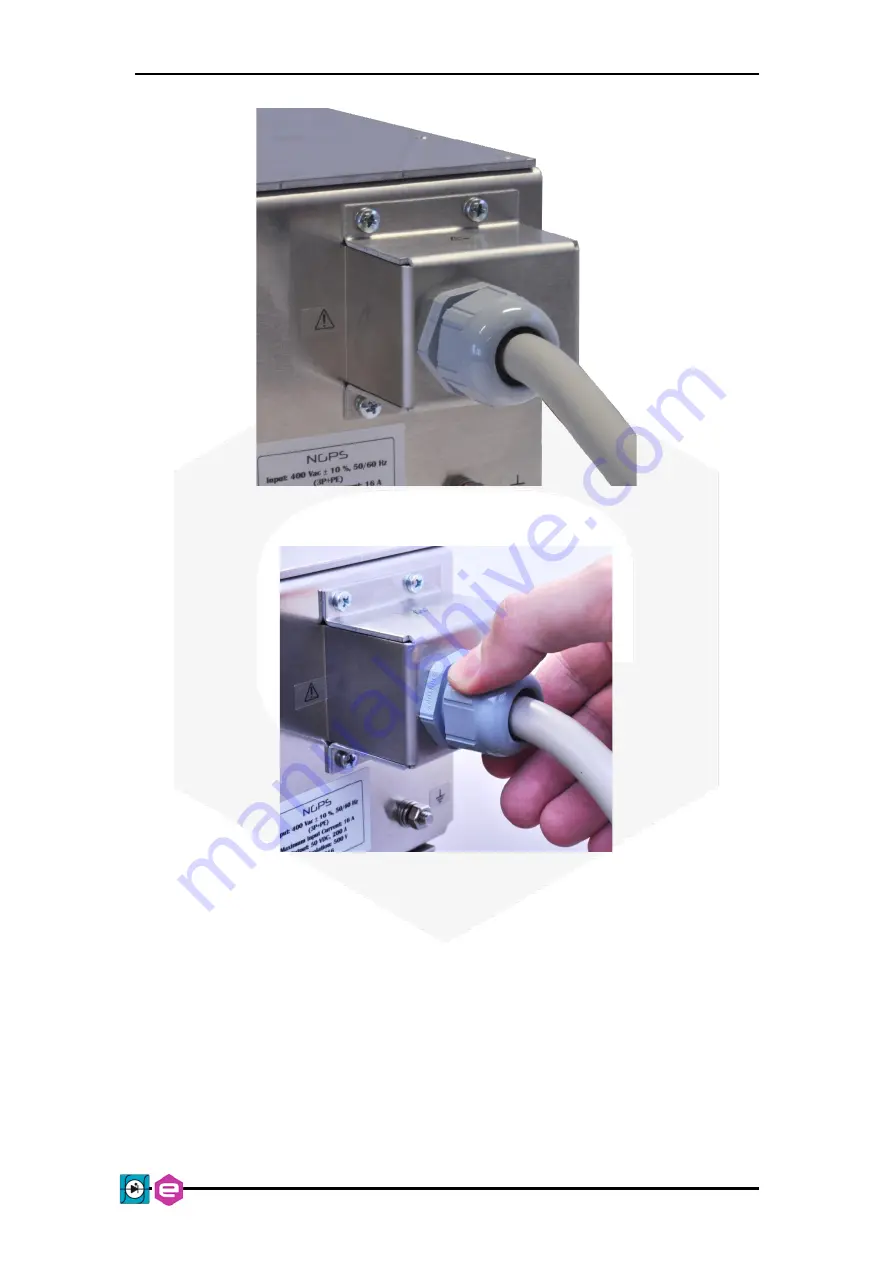
Figure 16
: Protective cover mounting
Figure 17
: AC mains cable fastener
Страница 1: ...s Manual 1 NGPS High Stability and High Precision New Generation Power Supply Series User s Manual All Rights Reserved CAEN ELS s r l Energy Technology s r l Rev 1 10 November 2022 MAGNET POWER SUPPL...
Страница 2: ...uct is compliant CAEN ELS s r l via Vetraia 11 55049 Viareggio LU Italy Mail info caenels com Web www caenels com OC Energy Technology s r l via della Solidarieta 2 1 40056 Valsamoggia BO Italy Mail p...
Страница 3: ...PS 160 60EH NGPS 200 25EH NGPS 160 30EH NGPS CQD 1100 5EH NGPS CQD 600 10EH NGPS CQD 600 15EH NGPS CQD 600 5EH NGPS CMD 150 70E NGPS CMD 200 50E NGPS CMD 300 30E NGPS CAI 300 18EH NGPS CAI 400 25EH NG...
Страница 4: ...rol Input 26 1 7 FRONT PANEL INDICATORS 27 1 8 INTERNAL PROTECTIONS 27 Earth Leakage Current 28 Earth Fuse 28 Regulation Fault 28 OVerPower OVP 29 OVerTemperature OVT 29 DC Link Undervoltage 30 1 9 CU...
Страница 5: ...NGPS User s Manual 5 Control Page 50 Config Page 50 Advanced Page 51 4 NGPS UTILITIES 53 5 MECHANICAL DIMENSIONS 54 6 TECHNICAL SPECIFICATIONS 56...
Страница 6: ...ganization 1 1 November 15th 2017 Added Auto shut down feature on Display 1 2 November 18th 2018 Added 100 100 model 1 3 February 25th 2019 Added 250 30 150 60 and 300 30 models Added parallel operati...
Страница 7: ...mentation must be consulted in all cases where this symbol is marked Indicates ground terminal Protective Ground Conductor Terminal Environmental Conditions Requirements Environment Indoor use Operati...
Страница 8: ...oduct within the guarantee period if the Guarantor declares that the product is defective due to workmanship or materials and has not been caused by mishandling negligence on behalf of the User accide...
Страница 9: ...NGPS User s Manual 9 Disposal of the Product The product must never be dumped in the Municipal Waste Please check your local regulations for disposal of electronics products...
Страница 10: ...plosives gas vapor or dust Always use the device with the provided cables Turn off the device before establishing any connection Do not operate the device with the cover removed or loosened Do not ins...
Страница 11: ...are enclosed in 19 inch crates with different unit height size depending upon space requirements of internal electronics Among custom models several options are available such as Auxiliary 230 Vac po...
Страница 12: ...9 NGPS 400 30E 400 30 12 NGPS CAX 100 100E 100 100 10 NGPS CAX 200 40E 200 40 8 NGPS CAX 200 50E 200 50 10 NGPS CVF 30 300E 30 300 9 Model Name Current A Voltage V Max Power kW NGPS 160 30EH 160 30 4...
Страница 13: ...mmunication is guaranteed by means of an Ethernet 10 100 1000 autosensing socket mounted on the front panel of the power unit The power supply can be also monitored and controlled via a graphic high r...
Страница 14: ...no differences between air and water cooled units of the NGPS power supply are placed a circuit breaker a colour graphic display with navigation switch for the local control and monitor of the module...
Страница 15: ...ter cooled NGPS rear view Plugs for the connection to the hydraulic system are highlighted The connectors used for water cooling are quick connecting types as follows The connectors are of model PLC42...
Страница 16: ...the PLCD17006 which is as follows Material Acetal Pressure Range Vacuum to 120 psi 8 3 bar Color White Temp Range 40 F to 180 F 40 C to 82 C Mounting Option Free Floating Seal Options BUNA N Valve Spr...
Страница 17: ...de it is possible to use the remote sensing terminals on the rear side that allow regulating the output voltage directly on the load thus compensating the voltage drops due to the output cables The ma...
Страница 18: ...oint is updated by an external event i e a hardware trigger coming from the rear BNC connector Please note that this mode of operation is obtainable only on the units that have the external trigger in...
Страница 19: ...ure 4 I O Connector The pin index of the D Sub 15 rear connector is summarized in the following table Pin Number Signal name 1 Interlock 1 return 2 Interlock 2 return 3 Interlock 3 return 4 Interlock...
Страница 20: ...ound that pins can sustain is 48 V The two interlocks inputs have their own return connection The interlock is hardware activated when the input pin and its corresponding return pin are shorted The sy...
Страница 21: ...to be at its activation level before tripping and thus generating a fault condition The intervention time parameters are stored from field 92 to 96 for Interlock 1 to 4 respectively Please refer to th...
Страница 22: ...e wire might cause damage to the power supply in local and remote sensing Do not connect S to or S to The NGPS mounts a voltage sensing connector on the rear panel that allows using the voltage sensin...
Страница 23: ...ed as well as S with This configuration performs the remote sensing directly at the output connector of the power unit Leaving S and S pins disconnected the remote sensing is still made but in a less...
Страница 24: ...In order to perform remote sensing at different points e g the load terminals it would be necessary to connect Pin 1 and Pin 4 as in Figure 7 Figure 7 Example of remote sensing NGPS LOAD S S Power Cab...
Страница 25: ...ompatible signals and should be driven by a low impedance source or generator The logic levels are subject to a hysteresis to guarantee the correct trigger operation as listed in Table 6 Logic Level V...
Страница 26: ...utput which is proportional to the input signal zero output for a 0V input and Full Scale output for a 10V input An example of the relation between the analog input signal and the output can be either...
Страница 27: ...ltage ALARM red if turned on it signals a fault condition experienced by the power unit It is necessary to perform a reset fault command in order to turn off this LED and to turn on the module output...
Страница 28: ...eeds to be replaced in order to get rid of the fault condition before resetting the NGPS internal status register The fuse holder is shown in Figure 12 Figure 12 Earth fuse holder In case of replaceme...
Страница 29: ...ng see Table 1a Standard NGPS models The module is able to work at a power comprised between 1 and 5 over its rating i e between 101 and 105 for a 20 seconds interval before turning off and tripping a...
Страница 30: ...ection is also called DC Link and it is proportional to the maximum rated voltage of the specific model A continuous monitoring of the DC Link voltage is performed in order to always guarantee the cap...
Страница 31: ...y 230 VAC 1 phase input connector is a plug filter which includes both a switch and fuse box and it is provided with two interchangeable fuses 5x20 mm rated at 2 A For the NGPS AUX models the single p...
Страница 32: ...NGPS User s Manual 32 Figure 14 NGPS AUX additional single phase input This connector presents the specifications as hereafter presented The PUSH IN connectors mates with standard Semi Rigid Polyamid...
Страница 33: ...ad connection Wire size selection remote sensing 5 Hydraulic Plugs Connection Exclusively for water cooled models 6 Output Grounding Grounding or floating output 7 First switch on Switch on checkout p...
Страница 34: ...d the air intake occurs at the front panel and the exhaust exits from the rear panel Upon installation allow cooling air to reach the front panel ventilation inlets Allow minimum 10 cm of unrestricted...
Страница 35: ...und via the safety ground in the AC input stud terminals The three phase input connector on the rear panel is a Phoenix Contact 1777749 PC 5 4 ST1 connector The three phase ground has to be connected...
Страница 36: ...l safety ground via the safety ground in the AC input connector Sizing of the Protective Earth Ground cable and check of the Protective Earth impedance coordination with electrical distribution system...
Страница 37: ...NGPS User s Manual Local Control 37 Figure 16 Protective cover mounting Figure 17 AC mains cable fastener...
Страница 38: ...tral and Earth and must not float 2 5 Load Connection Turn off the AC input power before making or changing any rear panel connection Ensure that all connections are securely tightened before applying...
Страница 39: ...n Table 10 Wire selection the maximum voltage applied to the load will be VDC N VS max Vcable Where VDC N NGPS nominal output voltage VS max Maximum compensation Voltage if Remote sensing is used N B...
Страница 40: ...negative polarity of the terminal respectively After securing both output connections it is necessary to mount the metallic protective cover since the power supply delivers high current and or hazardo...
Страница 41: ...th Leakage Fault Section 1 8 1 and Earth Fuse Fault Section 1 8 2 To allow floating operation of the output it is sufficient to remove the Earth Fuse from the fuse holder and set the power supply for...
Страница 42: ...ne module has to be configured as Master and all the others as Slaves Each step is described below HARDWARE CONNECTION 1 Each NGPS has to be properly mounted on a 19 rack N B do not connect AC main at...
Страница 43: ...NGPS User s Manual Local Control 43 3 Connect the SFP transceiver modules in daisy chain mode...
Страница 44: ...e modules to be paralleled Being a daisy chain the user can connect the optical cables plugs to SFP plugins in any order N B use the SFP1 connection on each module 4 Remove the earth fuse from each NG...
Страница 45: ...d the OFF ON selection on ON and then press Return on the right side 4 The other NGPSs have to be selected as Slave and the OFF ON selection on ON and then press Return 5 Perform a power cycle on both...
Страница 46: ...on interfaces when the unit is in LOCAL mode i e settings are inhibited The control mode LOCAL REMOTE can be set on the configuration page of the local menu 3 1 Navigation Switch Each NGPS power suppl...
Страница 47: ...tion switch By default the display will be automatically turned off after 30 minutes from the last local command or from the turning on of the power supply The user can disable this feature or change...
Страница 48: ...n without fault condition means that the power converter is Ready the status of the control i e Local LOC Remote REM Fast Control FCI the set regulation mode i e constant current C C or constant volta...
Страница 49: ...ol sub page once pressed it gives access to the main settings of the NGPS power supply unit Config sub page once pressed it allows the user to set the control regulation mode of the power supply Advan...
Страница 50: ...ut current or voltage C C or C V respectively Actual values of output current and output voltage readbacks are also shown at the bottom line of the display Config Page The Config Page is reachable by...
Страница 51: ...hernet IP address the Network Mask and the Gateway Figure 26 Network Page It is very important to notice that once the OK button has been clicked the user can remotely communicate and get again contro...
Страница 52: ...peratures and CPU usage Figure 29 System info Page REMARKS Heatsink 1 temp is the maximum temperature among the heatsinks to which the switching semiconductors are mounted Heatsink 2 temp refers to th...
Страница 53: ...oftware useful for the detection of the NGPS units connected to the local network as well as to check and eventually modify their network configuration as an alternative to the use of the local interf...
Страница 54: ...Mechanical Dimensions NGPS User s Manual 54 5 Mechanical Dimensions The mechanical dimensions of the air cooled NGPS unit are shown in Figure 30 Figure 30 Air cooled NGPS mechanical drawings...
Страница 55: ...NGPS User s Manual Technical Specifications 55 The mechanical dimensions of the water cooled NGPS unit are shown in Figure 31 Figure 31 Water cooled NGPS mechanical drawings...
Страница 56: ...osed loop Bandwidth 100 Hz C C mode 200 Hz C V mode Accuracy 0 01 0 005 upon request C C mode 0 05 C V mode Line Regulation 5 ppm FS Load Regulation 5 ppm FS Remote Sensing Compensation up to 2V Cooli...
Страница 57: ...ctive levels and timings Firmware remote update with password Dimensions 19 x 3U x 600 mm Input Ratings 208 VAC 10 A Three phase 50 60 Hz 400 VAC 10 E Three phase 50 60 Hz Weight 28 kg Enclosure impac...