


CT-BOX Viewer – Quick Start Guide
8
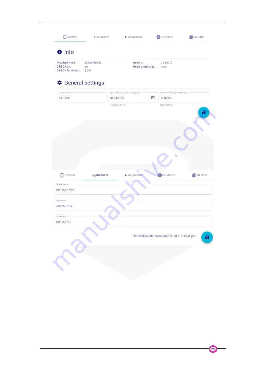
Figure 4:
General settings tab.
NETWORK
), it is possible to change the
IP address
of the
CT-BOX, the relative
netmask
and the
gateway
address. In case of any change, the
CT-BOX must be added again in the viewer by following the initial procedure
explained in
Sec. 2.1
Figure 5:
Network settings tab.
ACQUISITION
In the
ACQUISITION
), the user can select the operation mode
(among Data-Logger and Oscilloscope) and change the relative settings, namely:
•
when
Data-Logger
mode has been selected, it is possible to set (i) the
acquisition frequency
(expressed in [Hz], N.B. resolution is 0.1 Hz), (ii) to
choose whether if acquire or not the
head temperature
(i.e. matched DCCT)
and the
external temperature
(through an external temperature sensor), (iii) as
well as to save the acquired data on an eventual
SD card
(if it is not already
done, it mounts the SD card, see also the
SD Card Manger
part in this
section). Furthermore, at the bottom, by means of the refreshing icon, it is
possible to read the
instantaneous current
and to reset an eventual
offset
after a
power cycle of the CT-BOX. This last procedure must be performed when no
primary current is flowing.


