CAE Dynaco ST-70 Restoration Module Скачать руководство пользователя страница 8

Dynaco ST-70 Restoration Module 

Assembly, Installation, and Adjustment Manual


Page 8 

CAE Dynaco Driver Restoration Module PC-3R – R0: 7-02 


CAE Stereo 70 Restoration Module 

7-02    R0 


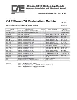
Stereo 70 Restoration Module, CAE# ASM-3R 

PAGE 1 of 1 


DESIG 

DESCRIPTION 

QNTY

PART NUMBER 

VAL / VOLT 

C1 & C2 

CAPACITOR, MYLAR or POLYPRO 


0.05uF/200VDC 

C3, C4, C5, C6 

CAPACITOR, MYLAR or POLYPRO 


0.1uF/400VDC 

C7 & C8 

CAPACITOR, MICA 

MSR#5982-5-300V390 

390pF, 5% 

C9 & C10 

CAPACITOR, MICA 

MSR#5982-5-300V82 

82pF, 5% 

R1, R2, R3, R4 

RESISTOR, METAL OXIDE 

DK#P47KW-3BK-ND 

47 K , 3W 

R5, R6 

RESISTOR, CARBON FILM 

MSR#29SJ500-18K 

18K, 1/2 W 

R7, R8, R9, R10 

RESISTOR, CARBON FILM 

MSR#29SJ500-270K 

270K, 1/2W 

R11 & R12 

RESISTOR, CARBON FILM 

MSR#29SJ500-10 

10, 1/2 W 

R13 & R14 

RESISTOR, METAL FILM 

MSR#29MF500-47.5 

47.5, 1/2 W 

R15 & R16 

RESISTOR, METAL OXIDE 

DK#P1KW-3BK-ND 

1 K , 3W 

R17 & R17 

RESISTOR, METAL OXIDE 

DK#P330KW-3BK-ND 

330 K , 3W 

R19 & R20 

RESISTOR, METAL OXIDE 

DK#P270KW-3BK-ND 

270 K, 3W 

R21 & R22 

RESISTOR, METAL FILM 

MSR#29MF500-620 

620, 1/2 W 

R22 & R23 

RESISTOR, CARBON FILM 

MSR#29SJ500-470K 

470K, 1/2 W 

R24 & R25 

RESISTOR, METAL FILM  

 MSR#29MF500-1.5M 

1.5 MEG, ½ W  

R26 & R27 

RESISTOR, METAL OXIDE 

DK#P18KW-3BK-ND 

18 K, 3 W 

V1 & V2 

PREMIUM TUBE 

7199 


X1 

PRINTED CIRCUIT BOARD 

CAE# PWB-3R 


X4 

PC BOARD TUBE SOCKETS, 9 PIN 

CAE# PC-9 


NOTES: 

CAE# - Curcio Audio Part Number 


DK# - DigiKey Part Number        MSR# - Mouser Part Number 


AES# - Antique Electronic Supply Part Number    


Содержание Dynaco ST-70 Restoration Module

Страница 1: ...particular Tech Note 1 II General Overview Take time to review all of the documentation provided including the aforementioned tech notes related to soldering technique and proper tools and test equip...

Страница 2: ...re associated with soldering related errors b Diodes transistors IC s all semiconductors and many capacitors always electrolytic types are polar this means that there is a right and wrong way to inser...

Страница 3: ...to Figure 1 Top View PC Board Component Placement Diagram The board has been designed so that a gentle radius near the body of the resistor will position the leads in alignment with the associated hol...

Страница 4: ...ext begin desoldering each wire from the original PC 3 card The original Dynaco wires were solid PVC insulated The PVC is not very tolerant of heat and therefore you should be very careful not to melt...

Страница 5: ...oard should be mounted so that the top surface of the PC Board rests inside the Dynaco ST 70 chassis cutout as per the original Be careful not to capture any wires and secure the board in places with...

Страница 6: ...ier tube and the two left channel output tubes Do not install the right channel output tubes right now Replace the original 3A fuse Rotate both original Bias Potentiometers fully counterclockwise Conn...

Страница 7: ...Dynaco ST 70 Restoration Module Assembly Installation and Adjustment Manual Page 7 CAE Dynaco Driver Restoration Module PC 3R R0 7 02 Figure 1...

Страница 8: ...R9 R10 RESISTOR CARBON FILM 4 MSR 29SJ500 270K 270K 1 2W R11 R12 RESISTOR CARBON FILM 2 MSR 29SJ500 10 10 1 2 W R13 R14 RESISTOR METAL FILM 2 MSR 29MF500 47 5 47 5 1 2 W R15 R16 RESISTOR METAL OXIDE 2...

Страница 9: ...Dynaco ST 70 Restoration Module Assembly Installation and Adjustment Manual Page 9 CAE Dynaco Driver Restoration Module PC 3R R0 7 02...

Страница 10: ...Dynaco ST 70 Restoration Module Assembly Installation and Adjustment Manual Page 10 CAE Dynaco Driver Restoration Module PC 3R R0 7 02...

Страница 11: ...Dynaco ST 70 Restoration Module Assembly Installation and Adjustment Manual Page 11 CAE Dynaco Driver Restoration Module PC 3R R0 7 02...

Отзывы: