4.
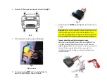
Remove the (4) 10mm screws securing radio to the dash (See
Fig. 3
)
Fig. 3
5.
Pull radio forward to reveal the connectors (See
Fig. 4
)
Fig. 4
Radio connectors
6.
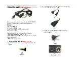
Disconnect factory 8-pin
GRAY
plug from radio (See
Fig. 4
) and
connect to 8-pin BLACK plug on harness (See
Fig. 5
)
Fig. 5
7.
Connect harness 8-pin
BLACK
plug (See
Fig. 6
) to radio chamber vacated
in step 6.
Warning:
Module is wired to receive 12V from radio amplifier turn on lead
(PIN 2-gray plug); however, radio may not provide enough current to
power both the module and Bose amplifier and as a result the module will
work intermittently. In this instance module must be powered elsewhere.
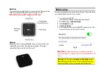
To power module from an alternate accessory source:
Disconnect terminal
(1)
and
(2).
Connect
(2)
to terminal
(3)
on 5ft red
wire. (
(1)
is
left unused. Route and connect red wire to 12V accessory
supply in vehicle available
under steering column inside driver's lower-dash
kick panel. Panel is supported by three bottom screws and three
metal/plastic clips at the top. Brown wire coming off ignition harness
provides ACC power.
Fig. 6
harness

