background image

17 


7


Operation 

After  the  charger  is  installed,  it  is  ready  for  charging  the  EVs.  The  following  describes  the 
operating elements and the display/indicators elements of the charger. 
 

7.1


Operating elements 

8.1.1


Display Areas 

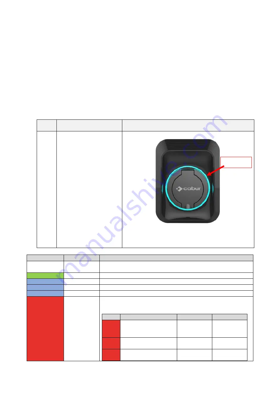
The charger has one display area AREA1, on its front side. 
A LED light belt is placed all around the charger socket and assumes different colours to indicate 
the current status 
 

Display 

Area 

Type 

Function description 

AREA1 

LED light belt  


Different  colours  indicate  the  current  status  of  the  charger  (see 
table below. 


Colour 

Blinking mode 

Status 

White 

No blinking 

Power on self test: the charger is switching on and performing the power on 
tests 

Green 

Blinking slowly 

Stand-By mode: the charger is on, available for charging 

Blue 

Fast blinking 

Pause during the charging process 

Blue 

No blinking 

Charging mode setup: the charger is preparing to start the charging process 

Blue 

Blinking slowly 

Charging mode: the charging process is ongoing 

Red 


Error mode: errors are detected by the internal protections. The table 
indicates the possible error cause and the way to recover 


Colour 

Blinking mode 

Description 

How to recover 

Red 

5 sec. period blinks 

CP Error: 

control pilot 

error 

Pull out the 

plug 

Red 

2.5 period blinks 

PE error: earth 

protection fault 

Turn the 

charger off 

Red 

Constant light, no blinking 

General fault 

Pull out the 

plug 


AREA 1 

Содержание EVCOMP7S

Страница 1: ...Cabur COMPACT EV Smart Chargers Installation and operating manual ...

Страница 2: ...ccessories 10 6 3 Installation of the protection against short circuit 10 6 4 Installation of the protection against residual current 11 6 5 Overvoltage protection 11 6 6 Installation cables 11 6 7 Supported power supply systems 11 6 8 Installation steps 12 7 Operation 17 7 1 Operating elements 17 8 1 1 Display Areas 17 8 System connectivity 18 8 1 WiFi interface 18 9 1 1 WiFi AP mode 18 9 1 2 Con...

Страница 3: ...2 Markings Point of contact under Directive 2014 35 EU Cabur S r L Località Isola Grande 45 17041 Altare SV Italy www cabur it ...

Страница 4: ...l 1 0 14 07 2021 Preliminary version New name Cabur_EV_COMPACT_Installation_Instruction_Manual 1 1 19 07 2021 Cabur Technical Office Updated cover Chapters 2 3 4 revised 1 2 03 08 2021 Cabur Technical Office Updated web app 1 3 20 11 2021 Cabur Technical Office Details for SSID connection updated Installation instructions updated ...

Страница 5: ...e product whenever needed The reproduction of this manual is not allowed without the written authorization by Cabur s r l 2 1 2 About safety The product conforms with the state of the art and the applicable safety and health regulations Nevertheless the following risks can be caused by incorrect operations or misuse Hazards to life and limb of the user or third parties Perils to the product and ot...

Страница 6: ...e charger It is prohibited to reconfigure or modify the product The product may only be operated in perfect conditions 2 1 3 About maintenance Do not open the charger Do not touch the electronic parts boards Do not install or use the charger if it is damaged The charger must be repaired by authorized personnel only Use a soft cloth with neutral detergent liquid suitable for plastic surfaces to cle...

Страница 7: ...The producer is also not liable for damage caused by the actions of third parties atmospheric discharges overvoltage and events related to chemical influences The warranty does not apply to the replacement of parts that are subject to natural wear and tear 4 Limits of use This charger is an electrical equipment designed for charging battery electric vehicles BEV The plug and the socket compliant t...

Страница 8: ... the operating conditions specified in the documentation This documentation is mandatorily to be read by qualified personnel for installation and initial operation as well as by the user for the Installation and Instruction Manual of the product For what concerns users unattended operation of the product is only allowed if they have read and understood this Installation and Instruction Manual have...

Страница 9: ...ocket Type 2 Dimensions W x H x D 160x126x210mm Weight 2 3kg Enclosure Material PC ASA UL94 V0 Cooling system Free air Mounting Wall Electrical Data Mains Voltage 230 V 15 single phase Mains Frequency 50 60Hz self adjustable Network Configuration TN TT IT 1P N PE or 2P PE 1 phase Efficiency 99 Earth Leakage Protection DC Leak 6ma ...

Страница 10: ...rvoltage protection Relay over temperature protection Socket or plug over temperature protection CP fault protection Relay adhesion protection IP Degree IP54 Ambient Temperature 25 C to 50 C Operating Humidity 95 RH Certificates Standards IEC 61851 1 2017 RED WiFi 2 4GHz RF EN 300 328 RF EMC EN 301 489 1 17 Health MPE EN 62311 CE Certificate CE from TUV The integrated protections are not automatic...

Страница 11: ...ture dust flammable gas flammable liquid etc away from heat sources and corrosive environments The altitude of the installation site must be 2000 m 6 2 Installation accessories The following accessories are needed for the charger installation process This manual The certificate of conformity The expansion screws 4 pieces provided with the charger to fix the charger to the wall The mounting templat...

Страница 12: ... device selection and installation must be performed by qualified personnel only 6 5 Overvoltage protection The charger is compliant to the Overvoltage Category III 6 6 Installation cables The cable for connecting the mains supply to the charger must have a section in the following range 6 10 mm2 The cable selection must be done by the qualified personnel involved in the installation process takin...

Страница 13: ...ttached to the charger rear side one rubber gland for the input cable 2 Lean the mounting template against the wall This will help to identify the correct positions of the screw holes on the wall The height from the centre of the template to the ground should be determined according to your ideal height 1500mm is recommended Check the template is fully horizontally aligned Mark the expansion screw...

Страница 14: ...d just push them manually or in case of resistance by means of an hammer 4 Open the front side removing the front cover The front cover can be removed just pressing the plastic blocks as in the picture 5 Turn the charger on the back side and remove the four screws of the wiring back cover ...

Страница 15: ... 20A 6 23A 7 25A 8 30A 9 32A If the rotating switch is set to 0 the output current configuration can be done through the web app using the Wi Fi AP connection In the other cases the configuration is fixed and cannot be adjusted through the web app interface 7 Make sure the input cable is not powered Prepare the supply input cables The rub stopper is not needed in case of 10mm2 cables The usage of ...

Страница 16: ...rt the supply cable while pushing the orange button with a flat screw driver The cable section must be 6mm2 or 10mm2 depending on the power value 9 The input cables can arrive from the upside or from the bottom side depending on the user s need 10 Close the wire cover Make sure the cover is fixed before switching the charger on ...

Страница 17: ...iption Picture 11 Mount the charger to the wall by using the four provided screws 12 Mount the front cover Make sure the cover is fixed before switching the charger on 13 The charger is installed and can be switched on ...

Страница 18: ...linking Power on self test the charger is switching on and performing the power on tests Green Blinking slowly Stand By mode the charger is on available for charging Blue Fast blinking Pause during the charging process Blue No blinking Charging mode setup the charger is preparing to start the charging process Blue Blinking slowly Charging mode the charging process is ongoing Red Error mode errors ...

Страница 19: ...d 9 1 1 WiFi AP mode The WiFi AP Access Point mode also referred as Hot Spot is mainly used for configuration and monitoring purposes In this mode the charger creates a WiFi network with a specified SSID and the user can connect to that network based on a point to point approach to apply all the necessary configurations or to monitor the charger parameters The connection to the charger can be esta...

Страница 20: ...19 Step No Description Picture 1 Scan for available WiFi networks with the connecting device utility ...

Страница 21: ...ated by the charger it should have an SSID name similar to ECxxxxxx xxxxxx Important note in case a login password is requested the default password is equal to the name of the SSID ECxxxxxx xxxxxx 5 Note only one device can be connected to the AP at a time 9 1 2 Configurations through WiFi AP mode ...

Страница 22: ...guration Step No Description Picture 1 The connecting device PC tablet smartphone is connected to the charger WiFi AP Open the internet browser Connect to the following URL http 192 168 1 1 The home page of the web app is shown 2 Standby button This button indicates the status of the charging process with its label Standby means the charger is not charging Stop charging means the charger is chargi...

Страница 23: ...r state button Pressing this button the user can access the charger state page to monitor all the parameters of the charger and their status The user can return back to the home page just clicking on the return button at the end of the page ...

Страница 24: ...the configuration main pages From this page the user can access other pages by clicking the 5 buttons at the top of the page These buttons will be explained later in the document System parameter settings In this page the main system parameters can be set Distribution system set the power distribution system the charger is connected to E Lock enables or disables the mechanical automatic interlock ...

Страница 25: ...yed with refresh Important note these parameters shall be configured by qualified personnel only 6 Clicking on the States button the user can access the page with the current status of the system parameters Clicking on the History button the user can access the historical logs of the device ...

Страница 26: ...ls Important note these parameters shall be configured by qualified personnel only 10 IT Power system this button enables the charger to be supplied by IT power network systems Other Power systems this button enables the charger to be supplied by TT or TN power network systems The selected power system is indicated by the different colour of the button after the selection Important note these para...

Страница 27: ...paragraph 9 1 2 point 1 a or directly by the car controls The connector can be unplugged only after the charging process stops Important note for the CASE B mode without the integrated cable there is an electronic lock inside the charger to keep the electrical connection stable during the charging process When charging is completed or a fault occurs the electronic lock will automatically unlock pl...

Страница 28: ...ions provided by the page itself to avoid failures in the process and make it complete in a successful way Important note these parameters shall be configured by qualified personnel only Important note Make sure not to disconnect during the upgrade process 4 Identify and select the upgrade file provided by the manufacturer it is typically a file named as name_of_the_upgrade_file bin This file can ...

Страница 29: ...sum_tool interface Then click the check button 6 A check sum MD5 value will automatically appear in the Checksum box the verification code generation is not necessary if the user already has the MD5 code provide by the manufacturer in this case the point 5 can be skipped The user shall now copy the value in the Checksum box 7 Now the user must be back to the system upgrade page in the web app The ...

Страница 30: ...tion with the same process illustrated in chapter 10 This system upgrade operation will not affect the system functionalities but will only change the language The user can upload the system upgrade file which contains his own language for example it is possible to have name_of_the_upgrade_file _IT bin IT italian language name_of_the_upgrade_file _EN bin EN english language name_of_the_upgrade_fil...

Отзывы: