background image

Chapter 3: Installation

3-4

2E42-27/2E42-27R/2E43-27/2E43-27R User’s Guide

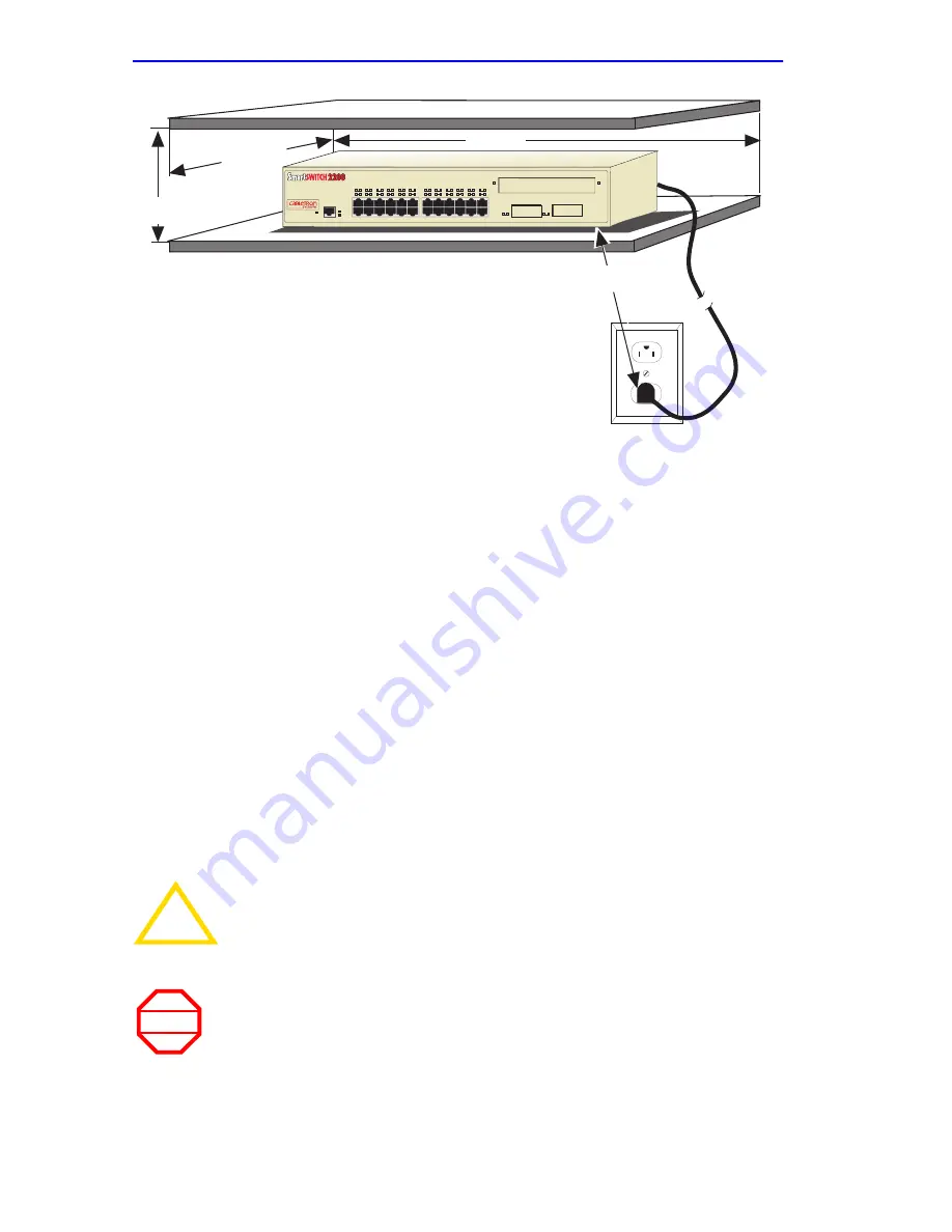
Figure 3-1

Tabletop or Shelf Installation

3.3.2

Rackmount Installation

To install the 2E4X-27 in a 19-inch rack, Cabletron Systems includes an 
accessory kit containing the rackmount brackets, mounting screws, and a 
strain-relief bracket for cable management.

Guidelines for the Rackmount Installation

The installation site must be within reach of the network cabling and meet 
the requirements listed below:

An appropriate grounded power receptacle must be located within 
seven feet of the location.

Maintain a temperature of between 5

°

C (41

°

F) and 40

°

C (104

°

F) at 

the installation site with fluctuations of less than 10

°

C (18

°

F) per hour.

!

CAUTION

To ensure proper ventilation and prevent overheating, leave a 
minimum clearance space of 5.1 cm (2.0 in) at the left, right, 
and rear of the 2E4X-27.

WARNING

Before installing the 2E4X-27


into a rack, ensure that the rack 

supports the device(s) without compromising the stability of the 
rack. Otherwise, personal injury and/or equipment damage 
may result.

1960-06

A = 15 cm (6 in)
B = 57 cm (22.5 in)
C = 53 cm (21 in)

C

B

A

D

D = 213 cm (7 ft)

1

2

3

4

5

6

7

8

11

12

13

14

15

16

9

10

17

18

19

20

21

22

23

24

COM

PWR
CPU

RESET

1X          3X          5X          7X          9X         11X             13X        15X      17X         19X       21X        23X

26

25

2E42-27

Содержание Spectrum 2E42-27

Страница 1: ...ch 2200 User s Guide 1 2 3 4 5 6 7 8 11 12 13 14 15 16 9 10 17 18 19 20 21 22 23 24 2E42 27 COM PWR CPU RESET 1X 3X 5X 7X 9X 11X 13X 15X 17X 19X 21X 23X 26 25 2E43 27 COM PWR CPU RESET 26 25 1 2 3 4 5...

Страница 2: ......

Страница 3: ...ed in this manual may be trademarks or registered trademarks of their respective companies FCC NOTICE This device complies with Part 15 of the FCC rules Operation is subject to the following two condi...

Страница 4: ...CI If this equipment is used in a domestic environment radio disturbance may arise When such trouble occurs the user may be required to take corrective actions CABLETRON SYSTEMS INC PROGRAM LICENSE AG...

Страница 5: ...TIAL DAMAGES IN NO EVENT SHALL CABLETRON OR ITS SUPPLIERS BE LIABLE FOR ANY DAMAGES WHATSOEVER INCLUDING WITHOUT LIMITATION DAMAGES FOR LOSS OF BUSINESS PROFITS BUSINESS INTERRUPTION LOSS OF BUSINESS...

Страница 6: ...mmission CENELEC EN 60825 European Committee for Electrotechnical Standardization When operating within their performance limitations laser transceiver output meets the Class 1 accessible emission lim...

Страница 7: ...3 EEC EN 55022 EN 50082 1 EN 60950 Equipment Type Environment Networking Equipment for use in a Commercial or Light Industrial Environment We the undersigned hereby declare under our sole responsibili...

Страница 8: ...Notice vi 2E42 27 2E42 27R 2E43 27 2E43 27R User s Guide...

Страница 9: ...8 Year 2000 Compliant 1 7 1 4 9 LANVIEW Diagnostic LEDs 1 7 1 4 10 Optional Features 1 8 1 5 Document Conventions 1 9 1 6 Getting Help 1 10 1 7 Related Manuals 1 11 CHAPTER 2 NETWORK REQUIREMENTS 2 1...

Страница 10: ...4 5 3 2 Management Terminal Setup Parameters 5 5 5 3 3 Monitoring an Uninterruptible Power Supply 5 6 5 4 Accessing Local Management 5 7 5 4 1 Navigating Local Management Screens 5 8 5 4 2 Selecting L...

Страница 11: ...00F3 Operational Mode 5 51 5 15 3 Configuring an FE 100TX in Port 25 or 26 5 51 5 15 4 Setting the FE 100TX Operational Mode 5 51 5 15 5 Setting the FE 100TX Advertised Ability 5 52 5 16 Flash Downloa...

Страница 12: ...Input Output Ports A 2 A 6 COM Port Pin Assignments A 3 A 7 Regulatory Compliance A 3 APPENDIX B FE 100TX FE 100FX AND FE 100F3 SPECIFICATIONS B 1 FE 100TX B 1 B 2 FE 100FX B 2 B 3 FE 100F3 B 3 APPEND...

Страница 13: ...CTURE OF THIS GUIDE This guide is organized as follows Chapter 1 Introduction outlines the contents of this manual and briefly describes the 2E4X 27 features Directions about how to obtain additional...

Страница 14: ...s and how to set the Mode Switch 1 3 2E4X 27 FEATURES Figure 1 1 shows the 2E42 27 and 2E43 27 Following the figure is a list of the features Figure 1 1 The 2E42 27 and 2E43 27 19601_01 RESET Button R...

Страница 15: ...anagement to provide a higher aggregate bandwidth between Cabletron Systems devices that support the SmartTrunk feature Runtime IPAddress Discovery which allows the 2E4X 27 to send out Reverse Address...

Страница 16: ...n a standard 19 inch rack using the supplied rack mounting hardware The 2E42 27 and 2E43 27 have one universal ac power supply with automatic voltage sensing that allows operation using 100 125 or 200...

Страница 17: ...le server or high end workstation connections The Fast Ethernet ports provide up to 200 Mbps of bandwidth 1 4 3 SmartTrunk SmartTrunk also referred to as SmartTrunking is Cabletron Systems terminology...

Страница 18: ...after every transmission until an interval of 300 seconds is reached At this point the interval remains at 300 seconds The RAD requests continue until an IP address is received from a BootP server or...

Страница 19: ...port to enhance the overall reliability of the network and protect against loop conditions The 2E4X 27 supports a wide variety of industry standard MIBs including RFC 1213 MIB II RFC 1757 RMON RFC 137...

Страница 20: ...rface Modules are listed in Table 1 1 High Speed Interface Modules HSIMs are available from Cabletron Systems for additional connectivity to various networking technologies The HSIMs available for the...

Страница 21: ...rmation that may be of special importance TIP Tip symbol Conveys helpful hints concerning procedures or actions CAUTION Caution symbol Contains information essential to avoid damage to the equipment E...

Страница 22: ...involved Cabletron Systems products in the network A description of your network environment layout cable type etc Network load and frame size at the time of trouble if known The device history i e ha...

Страница 23: ...hernet Technology Guide Cabletron Systems Cabling Guide Cabletron Systems Port Based VLAN User s Guide Cabletron Systems SmartTrunk User s Guide These manuals can be obtained from the World Wide Web i...

Страница 24: ...Chapter 1 Introduction 1 12 2E42 27 2E42 27R 2E43 27 2E43 27R User s Guide...

Страница 25: ...network performance 2 1 SmartTrunk To connect the 2E4X 27 to a network so it can take advantage of the SmartTrunk feature there are certain rules concerning port connections and configurations that m...

Страница 26: ...optic interface modules The device at the other end of the fiber optic segment must meet the 100BASE FX Fast Ethernet network requirements to operate at 100 Mbps Refer to the Cabletron Systems Cablin...

Страница 27: ...to install the device Follow the order of the sections listed below to correctly install the 2E4X 27 Unpacking the 2E4X 27 Section 3 1 Installing Options Section 3 2 Installing the 2E4X 27 on a shelf...

Страница 28: ...ny signs of damage Refer to Section 1 6 Getting Help for details 3 2 INSTALLING OPTIONS If the 2E4X 27 is to be installed with an optional Fast Ethernet Interface Module refer to Appendix C for instal...

Страница 29: ...lf installation the shelf must support 13 6 kg 30 lb of static weight for each 2E4X 27 Maintain a temperature of between 5 C 41 F and 40 C 104 F at the installation site with fluctuations of less than...

Страница 30: ...within seven feet of the location Maintain a temperature of between 5 C 41 F and 40 C 104 F at the installation site with fluctuations of less than 10 C 18 F per hour CAUTION To ensure proper ventila...

Страница 31: ...cket and four 8 32 x 3 8 inch pan head screws in the rackmount kit 2 Attach the strain relief bracket to the bottom of the 2E4X 27 using the four 8 32 x 3 8 inch pan head screws Figure 3 2 Figure 3 2...

Страница 32: ...s shown in Figure 3 3 Figure 3 3 Installing the Rackmount Brackets 3 With the mounting brackets installed position the 2E4X 27 between the vertical frame members of the 19 inch rack and fasten it secu...

Страница 33: ...the LANVIEW LEDs After a successful boot the CPU LED turns ON green If the CPU LED is not green after one minute check the power cord connection and power source If the CPU LED is still not green con...

Страница 34: ...ew 2 Observe the LANVIEW LEDs After a successful boot the CPU LED turns ON green If the CPU LED is not green after one minute and turns yellow there is no power redundancy Check the power cord connect...

Страница 35: ...Refer to Section 3 4 2 to make a UTP connection to an FE 100TX in port slot 25 or 26 Refer to Section 3 4 3 to make a fiber optic cable connection to an FE 100FX or FE 100F3 in port slot 25 or 26 Ref...

Страница 36: ...ther end of the segment is powered ON 2 Connect the twisted pair segment to the 2E42 27 by inserting the RJ45 connector on the twisted pair segment into the desired RJ45 port Ports 1 through 24 as sho...

Страница 37: ...shed contact the Cabletron Systems Global Call Center Refer to Section 1 6 for details 4 Repeat steps 1 through 3 above until all connections have been made 3 4 1 2 2E43 27 or 2E43 27R Cable Connectio...

Страница 38: ...lied with the device insert the RJ21 angle adapter as shown in Figure 3 9 The RJ21 angle adapter allows the cables to be dressed along the front of the device and easily attached to the strain relief...

Страница 39: ...the cable for continuity c Check that the twisted pair connection meets the dB loss and cable specifications outlined in Chapter 2 If a link is not established contact the Cabletron Systems Global Ca...

Страница 40: ...d of the segment is powered ON 2 Connect the twisted pair segment to the module by inserting the RJ45 connector on the twisted pair segment into the RJ45 port on the module shown in Figure 3 10 3 Veri...

Страница 41: ...es so that the transmit port of one device is connected to the receive port of the other device and vice versa If the fiber optic cable being used has SC style connectors that do not resemble MIC styl...

Страница 42: ...ing green or solid green If the RX LED is OFF and the TX LED is not blinking yellow perform the following steps until it is on a Check that the power is turned on for the device at the other end of th...

Страница 43: ...M as appropriate and making the connections to the network proceed as follows 1 Secure the cables by running the cables along the strain relief bracket and tying them to the strain relief bracket usin...

Страница 44: ...Chapter 3 Installation 3 18 2E42 27 2E42 27R 2E43 27 2E43 27R User s Guide...

Страница 45: ...s monitoring system called LANVIEW The LANVIEW LEDs Figure 4 1 allow quick observation of the network status to aid in diagnosing network problems Refer to Table 4 1 for a description of the LEDs For...

Страница 46: ...mally No action Amber Indicates loss of power supply redundancy This indication only applies when there are two power supplies 1 Ensure that the power cords are plugged in correctly and that there is...

Страница 47: ...dicating BPDUs being sent if STA is enabled and there is a valid link 1 Ensure that the STA is enabled and that there is a valid link 2 Contact the Cabletron Systems Global Call Center for help Green...

Страница 48: ...The 10 100 LED and the Receive RX LED are shown in Figure 4 2 Table 4 2 and Table 4 3 provide a functional description of the 10 100 LED when the RX LED is on or off respectively Figure 4 2 FE 100TX...

Страница 49: ...X LED Is Off NOTE No link exists if the associated port 25 or 26 RX Receive LED is off LED Color Indication 10 100 Off No link or no cable attached FE 100TX forced to 10 Mbps operation or is manually...

Страница 50: ...e port pinouts Cannot contact the device from in band management Improper Community Names Table Refer to Chapter 5 for Community Names Table setup IP address not assigned Refer to Chapter 5 for IP add...

Страница 51: ...r use a pen or pencil to press and release the RESET button The 2E4X 27 goes through a reset process for approximately 45 seconds CAUTION Pressing the RESET button resets the device and all current sw...

Страница 52: ...Chapter 4 Troubleshooting 4 8 2E42 27 2E42 27R 2E43 27 2E43 27R User s Guide...

Страница 53: ...t a default gateway Control access by establishing community names Download a new image of the operation software Designate which Network Management Workstations receive SNMP traps from the device Vie...

Страница 54: ...aving changes For example Press ESC twice means the ESC key must be pressed quickly two times SPACE Bar BACKSPACE Key These keys cycle through selections in some Local Management fields Use the SPACE...

Страница 55: ...tems to access Local Management An IBM or compatible PC running a VT series emulation software package A Digital Equipment Corporation VT100 type terminal A VT type terminal running emulation programs...

Страница 56: ...s 1 Connect the RJ45 connector at one end of the cable supplied in the kit to the COM port on the 2E4X 27 2 Plug the RJ45 connector at the other end of the cable into the RJ45 to DB9 adapter supplied...

Страница 57: ...ursor Underline Cursor Style General Setup Menu Mode ID number Cursor Keys Power Supply VT100 7 Bit Controls VT100ID Normal Cursor Keys UPSS DEC Supplemental Communications Setup Menu Transmit Receive...

Страница 58: ...d to attach the UPS to the 2E4X 27 COM port as shown in Figure 5 2 To connect the UPS device to the COM port of the 2E4X 27 proceed as follows 1 Connect the RJ45 connector at one end of the cable to t...

Страница 59: ...e terminal Press ENTER this may take up to four times because the COM port auto senses the baud rate of the terminal until the 2E4X 27 Local Management Password screen displays It is the automatic lin...

Страница 60: ...priate figure that relates to the Operational Mode set for the device to see the applicable Local Management screen hierarchy NOTE The User s password is one of the community names specified in the SN...

Страница 61: ...rfaces HSIM Switch Statistics Interface Statistics RMON Statistics SmartTrunk Configuration Ethernet Full Duplex Configuration General Configuration SNMP Community Names SNMP Traps Switch Configuratio...

Страница 62: ...ocal Management LM screens Using the Exit Command To exit LM using the EXIT screen command proceed as follows 1 Use the arrow keys to highlight the EXIT command at the bottom of the Local Management s...

Страница 63: ...the Local Management hierarchy displays 3 Exit from 2E4X 27 Local Management by repeating steps 1 and 2 until the Device Menu screen displays 4 To end the LM session use the arrow keys to highlight th...

Страница 64: ...that are used to configure the 2E4X 27 and also to the Device Specific Configuration Menu screen The Device Specific Configuration Menu screen provides access to the screens that allow the user to ch...

Страница 65: ...4X 27 For details about this screen refer to Section 5 19 NETWORK TOOLS The Network Tools function resides on the 2E4X 27 and consists of a series of commands that allow the user to access and manage...

Страница 66: ...Configuration Menu screen displays Figure 5 8 Device Configuration Menu Screen NOTE The following menu items on the Device Configuration Menu screen may not display if the operational mode of the devi...

Страница 67: ...y names For details refer to Section 5 9 SWITCH CONFIGURATION The Switch Configuration screen provides the basic setup options for modifying switch operation in the network For details refer to Sectio...

Страница 68: ...ld MAC Address Read Only Displays the physical address of the 2E4X 27 IP Address Modifiable Displays and allows the user to set the IP address for the 2E4X 27 To set the IP address refer to Section 5...

Страница 69: ...on 5 7 4 Device Date Modifiable Contains a value that the device recognizes as the current date To set a new device date refer to Section 5 7 5 Device Time Modifiable Contains a value that the device...

Страница 70: ...ith the Cabletron Systems VLAN Manager software the device is able to increase its switching functionality by creating and maintaining VLANs For details on how to select the Operational Mode refer to...

Страница 71: ...hat exceed the maximum Ethernet frame size will be discarded For details on enabling IP Fragmentation refer to Section 5 7 12 5 7 1 Setting the IP Address To set the IP address perform the following s...

Страница 72: ...efault perform the following steps 1 Use the arrow keys to highlight the Subnet Mask field 2 Enter the subnet mask into this field using Dotted Decimal Notation DDN format For example 255 255 0 0 3 Pr...

Страница 73: ...way If the SNMP management station is located on a different IP subnet than the 2E4X 27 a default gateway must be specified When an SNMP Trap is generated the 2E4X 27 sends the Trap to the default gat...

Страница 74: ...is located on a different IP subnet than the 2E4X 27 a Gateway IP address should be specified To set the TFTP Gateway IP address perform the following steps 1 Use the arrow keys to highlight the TFTP...

Страница 75: ...arrow keys to highlight the Device Time field 2 Enter the time in a 24 hour format HH MM SS 3 Press ENTER to set the system clock to the time in the input field 4 Use the arrow keys to highlight the...

Страница 76: ...If the entry is not valid Local Management does not alter the current setting but it does refresh the Screen Refresh Time field with the previous value 5 7 8 Setting the Screen Lockout Time The screen...

Страница 77: ...e SPACE bar to step to the appropriate operation mode 802 1D SWITCHING 802 1Q SWITCHING or SECURE FAST VLAN 3 Use the arrow keys to highlight the SAVE command then press ENTER The warning screen shown...

Страница 78: ...ollows 1 Use the arrow keys to highlight the Com field NOTE If the 2E4X 27 is set to 802 1Q SWITCHING refer to your Port Based VLAN User s Guide to configure the devices for this type of operation If...

Страница 79: ...e Local Management session If the 2E4X 27 was previously assigned a valid IP address reenter Local Management by establishing a Telnet connection to the device If the device does not have a valid IP a...

Страница 80: ...s LM To change the COM port application 1 Use the arrows keys to highlight the Application field 2 Use the SPACE bar or BACKSPACE to step through the available settings until the operation you require...

Страница 81: ...he warning screen shown in Figure 5 14 displays CAUTION When the COM port is configured to perform the UPS application all future Local Management connections must be made by establishing a Telnet con...

Страница 82: ...SPACE bar to choose either ENABLED or DISABLED 3 Use the arrow keys to highlight the SAVE command 4 Press ENTER SAVED OK displays in the Event Message Line at the top of the screen CAUTION If the 2E4...

Страница 83: ...nity Names screen from the Device Configuration Menu screen use the arrow keys to highlight the SNMP COMMUNITY NAMES menu item and press ENTER The SNMP Community Names screen displays Figure 5 15 SNMP...

Страница 84: ...write access to the 2E4X 27 MIB objects excluding security protected fields for Super User access only super user This community name gives the user read write access to the 2E4X 27 MIB objects and a...

Страница 85: ...in the field maximum 31 characters 3 Press ENTER 4 Repeat steps 1 through 3 to modify the other community names 5 Use the arrow keys to highlight SAVE at the bottom of the screen and press ENTER The...

Страница 86: ...owing explains each field of the SNMP Traps screen Trap Destination Modifiable Indicates the IP address of the workstation to receive trap alarms Up to eight different destinations can be defined Trap...

Страница 87: ...79 121 3 Press ENTER If an invalid entry is entered INVALID IP ENTERED is displayed in the Event Message Line 4 Use the arrow keys to highlight the Trap Community Name field Enter the community name 5...

Страница 88: ...n screen Switch Address Read Only Displays the MAC address of the switch NOTE The Switch Configuration screen is not available if the operational mode of the device is set to SECURE FAST VLAN This scr...

Страница 89: ...ult value of 300 seconds refer to Section 5 10 2 Port Read Only Lists each switched port on the device If the number of ports is greater than eight then the additional ports are listed on subsequent s...

Страница 90: ...E bar to step to the appropriate setting IEEE DEC or NONE 3 Use the arrow keys to highlight the SAVE command at the bottom of the screen 4 Press ENTER The message SAVED OK is displayed 5 10 2 Setting...

Страница 91: ...c Configuration Menu screen use the arrow keys to highlight the ETHERNET FULL DUPLEX CONFIGURATION menu item in the Device Specific Configuration Menu screen and press ENTER The Ethernet Full Duplex C...

Страница 92: ...0 Mbps thus enabling the port to effectively switch at 20 Mbps To set Ethernet ports for Full Duplex operation refer to Section 5 11 1 LINK STATUS Read only Indicates whether there is a physical conne...

Страница 93: ...e may be set to Standard Ethernet or Full Duplex either one port at a time or all at once The following steps describe setting the port Operational Mode for individual ports followed by steps to set t...

Страница 94: ...t one of five screens to configure ports or check system resources specific to the 2E4X 27 To access the Device Specific Configuration Menu screen from the Device Configuration Menu screen use the arr...

Страница 95: ...mount of available memory and provides information on 2E4X 27 operation For details refer to Section 5 13 HIGH SPEED INTERFACE CONFIGURATION The High Speed Interface Configuration screen provides acce...

Страница 96: ...tion 5 11 1 Setting the Operation Mode The Broadcast Suppression screen allows the user to set a desired limit of received broadcast frames that will be forwarded per port per second For details refer...

Страница 97: ...Memory Installed Read only Indicates the amount of FLASH memory installed in the 2E4X 27 and how much is currently available DRAM Installed Read only Indicates the amount of DRAM installed in the 2E4X...

Страница 98: ...ak Switch Utilization field to the current system traffic 5 13 1 Setting the Reset Peak Switch Utilization To set the Reset Peak Switch Utilization field to YES or NO proceed as follows 1 Use the arro...

Страница 99: ...h Speed Interface Configuration Menu screen FAST ETHERNET INTERFACES Displays the types of interfaces installed in ports 25 and 26 their current operating mode and indicates if the ports are linked Th...

Страница 100: ...hlight the FAST ETHERNET INTERFACES menu item and press ENTER The High Speed Interface Configuration screen displays Figure 5 22 High Speed Interface Configuration Screen NOTE The High Speed Interface...

Страница 101: ...connection from this port to another 10BASE T or 100BASE TX FX device One of the following values displays Link There is a link signal present and a valid physical connection to another device No Lin...

Страница 102: ...is 100BASE TXFD 100BASE TX 10BASE TFD and 10BASE T Advertised Ability Selectable During auto negotiation the FE 100TX tells the device at the other end of the segment about its capabilities The capabi...

Страница 103: ...00Base FXFD full duplex 3 Press ENTER The port now operates in the chosen mode 4 Use the arrow keys to highlight the SAVE command Press ENTER The message SAVED OK displays and Local Management saves t...

Страница 104: ...rk Administrator may want the port to advertise only some of the available modes and not advertise in other modes This field steps to 10Base T 10Base TFD full duplex 100Base TX and 100Base TXFD full d...

Страница 105: ...d Screen NOTE The user may also force the download of an image by changing the position of Switch 6 located inside the device Refer to Section C 2 1 Setting the Mode Switch for details NOTE For inform...

Страница 106: ...omplete If a Runtime Download is performed this field toggles between YES and NO If YES is selected the device reboots after the download is completed If NO is selected the device continues using the...

Страница 107: ...o the same IP address set in the TFTP Gateway IP Addr field in the General Configuration screen 5 Use the arrow keys to highlight EXECUTE at the bottom of the screen and press ENTER The message BOOTP...

Страница 108: ...2E4X 27 using Runtime proceed as follows 1 Use the arrow keys to highlight the Download Method field 2 Use the SPACE bar to select RUNTIME 3 Use the arrow keys to highlight the Reboot After Download...

Страница 109: ...age stored on the download server For example tftpboot 2E42 fls 11 Use the arrow keys to highlight EXECUTE at the bottom of the screen and press ENTER The message TFTP DOWNLOAD WILL COMMIT TO FLASH RE...

Страница 110: ...particular port s where with the use of an analyzer or RMON probe all current traffic from the source port s can be examined To access the Port Redirect Function screen from the Device Specific Config...

Страница 111: ...responding source ports are configured ON to send errored frames to the destination ports or OFF to drop all errored frames and only forward traffic without errored frames to the destination ports Sou...

Страница 112: ...ommand displays at the bottom of the first screen In the second screen the NEXT and PREVIOUS commands are displayed In the last screen only the PREVIOUS command is displayed To display the next screen...

Страница 113: ...SCREEN The Broadcast Suppression screen Figure 5 25 allows the user to set a desired limit of receive broadcast frames that are switched out to the other ports NOTE To redirect more than one port rep...

Страница 114: ...ne second interval Time Since Peak Read Only Displays the time since peak rate was achieved Firmware Revision XX XX XX Broadcast Statistics 19601 56 Device Type 2E42 27 BOOTPROM Revision XX XX XX PORT...

Страница 115: ...ts 13 through 24 While on the second screen the user can navigate back to the first screen by highlighting the 1 12 field and pressing ENTER The user can change the Threshold or Reset Peak fields whil...

Страница 116: ...at allow the user to obtain switch statistics about frame traffic through each interface and view operating statistics about each port To access the Device Statistics Menu from the Device Menu screen...

Страница 117: ...5 20 INTERFACE STATISTICS The Interface Statistics screen provides the MIB II statistics for each switched network interface on a interface by interface basis For details refer to Section 5 21 RMON S...

Страница 118: ...fields Interface Read Only Identifies the interface or port number NOTE The Switch Statistics screen is not available if the operational mode of the device is set to SECURE FAST VLAN This screen may...

Страница 119: ...ep to a second or third screen for the same type of information for ports 13 through 24 or 25 through 27 While on the second or third screen the user can navigate back to earlier screens by highlighti...

Страница 120: ...ing 1 This represents the 10 Mbps interface of CONN 1 To view other interface statistics refer to Section 5 21 1 Name Read Only The Name field displays the type of interface for which statistics are b...

Страница 121: ...ven though the frames contained no errors This field may increment because it was in an initialization phase and not ready to forward frames the switch needed to free up buffer space or the switch was...

Страница 122: ...d frames regardless of the cause of the error OutQLen Read Only The OutQLen field displays the length of the frame queue The field represents the total number of frames contained in queue Address Read...

Страница 123: ...nd refer to Section 5 21 1 CLEAR COUNTERS Command This command is used to reset all statistic counters to zero For details on how to use this field refer to Section 5 21 2 5 21 1 Displaying Interface...

Страница 124: ...t that gathers statistics for each of its interfaces Data Source Read only This field displays the source of the statistics data that is currently being displayed on the screen Figure 5 29 shows that...

Страница 125: ...ess The value of this field does not include multicast frames Multicasts Read only The Multicast field displays the total number of good frames received that were directed to a multicast address The v...

Страница 126: ...r a bad CRC Total Packets Read only This field displays the total number of frames including bad frames broadcast frames and multicast frames received on this interface Total Octets Read only This fie...

Страница 127: ...tets Read only Displays the total number of frames including bad frames received that were between 1024 and 1518 bytes in length excluding framing bits but including FCS bytes Index nn Command This co...

Страница 128: ...ow keys to highlight the CLEAR COUNTERS field 2 Press ENTER the counters for the selected index are reset to zero 5 23 NETWORK TOOLS The Network Tools function allows the user to access and manage net...

Страница 129: ...command set Built in Commands Allow the user to access and manage network devices The commands are arp bridge defroute netstat ping reset show traceroute soft reset telnet link_trap and atm_stp_state...

Страница 130: ...Lists any additional fields in the appropriate format which may be added to the command Example Shows an example of the command NOTE The conventions used in describing the commands in Network Tools ar...

Страница 131: ...lists the network interface that the device is connected to the device s network address or IP address the device s physical address or MAC address and the media type of connection to the device Media...

Страница 132: ...ber will affect the bridging status of that interface while specifying ALL will affect every interface Options Not Applicable Example arp a Interface 30 30 30 30 Network Address 122 144 40 111 122 144...

Страница 133: ...ace number IP address defroute delete interface number IP address Description The defroute command allows the user in the syntax order shown above to view set or delete the default IP route to a manag...

Страница 134: ...acd MTU 1514 1514 1514 1514 MAC Addr 0x00 0x00 0x1d 0x07 0x50 0x0e 0x00 0x00 0x1d 0x07 0x50 0x0f 0x00 0x00 0x1d 0x07 0x50 0x10 0x00 0x00 0x1d 0x07 0x50 0x11 Admin up up up up netstat r 05141 70 Speed...

Страница 135: ...ializes the CPU processor runs the onboard diagnostics and restarts the software image which restores the user configuration settings from NVRAM The user will be queried to confirm the reset command t...

Страница 136: ...address and provides a display of all next hop routers in the path to the device If the device is not reached the command displays all next hop routers to the point of failure Options Not Applicable s...

Страница 137: ...tings from NVRAM The user will be queried to confirm the reset command to ensure against unwanted resets Options Not Applicable Example TIP The Network Tools connection to the device will be terminate...

Страница 138: ...er is specified telnet will attempt to contact the host at the default port Options Not Applicable Example link_trap Syntax link_trap enable disable status PORT all Description The link_trap command a...

Страница 139: ...stp_state command is only available if an HSIM A6DP is installed in the device e g 6E13X 25 This command allows the user to enable disable or check the current status of the Spanning Tree Algorithm on...

Страница 140: ...7R User s Guide 5 23 2 Special Commands done quit exit Syntax done quit or exit Description The done quit or exit command enables the user to exit from Network Tools and return to the Main Menu screen...

Страница 141: ...ATIONS A 2 PHYSICAL PROPERTIES A 3 ELECTRICAL SPECIFICATIONS Processor Intel i960 RISC processor Dynamic Random Access Memory DRAM 16 MB FLASH Memory 4 MB Dimensions 7 11H x 43 18W x 46 99D cm 2 8H x...

Страница 142: ...ing 2E42 27 and 2E42 27R Ports 1 through 24 Ethernet 10BASE T compliant with 24 RJ45 type connectors 2E43 27 and 2E43 27R Ports 1 through 24 Ethernet 10BASE T compliant with RJ21 type connectors Each...

Страница 143: ...PLIANCE Table A 1 COM Port Pin Assignments Pin Signal Name Input Output 1 Transmit Data XMT Output 2 Data Carrier Detect DCD Output 3 Data Set Ready DSR Input 4 Receive Data RCV Input 5 Signal Ground...

Страница 144: ...Appendix A Specifications A 4 2E42 27 2E42 27R 2E43 27 2E43 27R User s Guide...

Страница 145: ...sover status of the cable pairs If the switch is on the X side the pairs are internally crossed over If the switch is on the side the pairs are not internally crossed over Figure B 1 shows the pinouts...

Страница 146: ...rst Case Budget Typical Budget 50 125 m fiber optic 6 0 dB 9 0 dB 62 5 125 m fiber optic 9 0 dB 12 0 dB 100 140 m fiber optic 15 0 dB 18 0 dB NOTE The transmitter power levels and receive sensitivity...

Страница 147: ...se Budget Typical Budget 8 125 m fiber optic 10 0 dB 10 0 dB 12 5 125 m fiber optic 10 0 dB 10 0 dB NOTE The transmitter power levels and receive sensitivity levels listed are peak power levels after...

Страница 148: ...Appendix B FE 100TX FE 100FX and FE 100F3 Specifications B 4 2E42 27 2E42 27R 2E43 27 2E43 27R User s Guide...

Страница 149: ...ace Module This appendix covers the following items Required tools Section C 1 Removing the chassis cover Section C 2 Locations functions and settings for the mode switches Section C 2 1 Installing Op...

Страница 150: ...D TO THE UNIT HAZARDOUS VOLTAGES ARE PRESENT AND COULD CAUSE PERSONAL INJURY AND OR DAMAGE THE UNIT DO NOT POWER UP THE 2E4X 27 AGAIN UNTIL THE COVER AND SCREWS ARE IN PLACE DECKEL VON DAS 2E4X 27 NIC...

Страница 151: ...UPPLY CORD DISCONNECT TWO POWER SUPPLY CORDS BEFORE SERVICING TO AVOID ELECTRIC SHOCK VORSICHT DIESES GER T HAT MEHR ALS EINEN NETZANSCHLU TRENNEN SIE VOR WARTUNGSARBEITEN DIE 2 NET ZANSCHL SSE VOM NE...

Страница 152: ...ff of the chassis To reinstall the chassis cover perform the removal procedures in reverse Figure C 1 Removing the Chassis Cover C 2 1 Setting the Mode Switch Figure C 2 shows the location of the mode...

Страница 153: ...The BootP server references the location of a station acting as a Trivial File Transfer Protocol TFTP server containing the 2E4X 27 image file When the position of Switch 6 is changed and the power i...

Страница 154: ...s device names etc are reset to the factory default settings Once the 2E4X 27 resets you can either use the factory default settings or re enter your own parameters Switch 8 Reset Password Community S...

Страница 155: ...igh Speed Interface Module for port 27 Figure C 3 Fast Ethernet Interface Module Connector Location 19601 11 Optional Fast Ethernet Interface Modules Connectors FRONT PANEL TOP VIEWS WITHOUT COVER Opt...

Страница 156: ...ace Modules are in the associated user s guide CAUTION The FE 100F3 uses Class 1 lasers Do not use optical instruments to view the laser output The use of optical instruments to view laser output incr...

Страница 157: ...Fast Ethernet Interface Modules to be aligned over the connector CAUTION When installing an FE 100FX or FE 100F3 module into the 2E4X 27 remove the rubber plug on the module before proceeding CAUTION...

Страница 158: ...Figure C 5 Installing the Fast Ethernet Interface Module 5 Press down firmly on the Fast Ethernet Interface Module until the pins slide all the way into the motherboard connector Ensure that the Fast...

Страница 159: ...F 2 2 100BASE T network 2 1 100BASE TX network 2 2 Chassis Cover removal of C 2 COM port 5 26 pin assignments A 3 Com Port Application 5 28 Command Set 5 77 Connecting to the network 3 9 Crossover swi...

Страница 160: ...46 High Speed Interface screen advertised ability 5 50 configuring an FE 100FX 5 51 configuring an FE 100TX 5 51 current operational mode 5 49 desired operational mode 5 50 link status 5 49 port type...

Страница 161: ...ing of 5 76 NVRAM clearing of 5 29 P Password screen 5 7 Passwords 5 31 Physical properties A 1 Port Redirect Function screen destination port 5 59 remap errors 5 59 source port 5 59 R Regulatory Comp...

Страница 162: ...ational mode for 5 25 Setup of management terminal 5 5 SmartTrunk introduction to 1 5 SNMP Community Names screen 5 31 access policy 5 32 community name 5 32 SNMP Traps screen 5 34 enable traps 5 35 t...

Страница 163: ...Index 2E42 27 2E42 27R 2E43 27 2E43 27R User s Guide Index 5 Troubleshooting 4 1 checklist 4 6 U Uninterruptible Power Supply connection of 5 6 Unpacking 3 2 V VLAN configuration of 5 44...

Страница 164: ...Index Index 6 2E42 27 2E42 27R 2E43 27 2E43 27R User s Guide...

Отзывы: