background image

A-9

9H423-26 Cabling Requirements

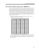
Return Loss (SRL).


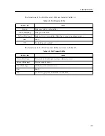
Refer to Table A-4. To be labeled as Category 5, the following 

SRL values must be satisfied.

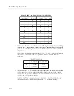
Attenuation - Attenuation refers to the amount of signal level degradation 
through a medium. This can be caused from impurities in the cable, and 
therefore the signal will not propagate as far. The following table lists the 
maximum attenuation (dB) per cable pair at 20° C. Refer to Table A-5.


Table A-4. UTP Cable SRL

Freq. f (MHz)

CAT 3 (dB)

CAT 4 (dB)

CAT 5 (dB)

1-10

12

21

23

10-16

12

log

(

f

/10)

21-10

log

(

f

/10)

23

16-20

-

21-10

log

(

f

/10)

23

20-100

-

-

23-10

log

(

f

/20)

Table A-5. Cable Attenuation per 100 m

Freq (MHz)

CAT 3 (dB)

CAT 4 (dB)

CAT 5 (dB)

0.064

0.9

0.8

0.8

0.256

1.3

1.1

1.1

0.512

1.8

1.5

1.5

0.772

2.2

1.9

1.8

1

2.6

2.2

2.0

4

5.6

4.3

4.1

8

8.5

6.2

5.8

10

9.7

6.9

6.5

16

13.1

8.9

8.2

20

-

10.0

9.3

25

-

-

10.4

31.25

-

-

11.7

62.5

-

-

17.0

100

-

-

22.0

Содержание SmartSwitch 9000

Страница 1: ...SmartSwitch 9000 9H423 26 User s Guide 9032242 02 ...

Страница 2: ......

Страница 3: ...DAMAGES WHATSOEVER INCLUDING BUT NOT LIMITED TO LOST PROFITS ARISING OUT OF OR RELATED TO THIS MANUAL OR THE INFORMATION CONTAINED IN IT EVEN IF CABLETRON SYSTEMS HAS BEEN ADVISED OF KNOWN OR SHOULD HAVE KNOWN THE POSSIBILITY OF SUCH DAMAGES Copyright March 1998 by Cabletron Systems Inc 35 Industrial Way Rochester NH 03867 5005 All Rights Reserved Printed in the United States of America Order Numb...

Страница 4: ...in which case the user will be required to correct the interference at his own expense WARNING Changes or modifications made to this device which are not expressly approved by the party responsible for compliance could void the user s authority to operate the equipment VCCI Notice This is a Class A product based on the standard of the Voluntary Control Council for Interference by Information Techn...

Страница 5: ...g Equipment for use in a Commercial or Light Industrial Environment We the undersigned hereby declare under our sole responsibility that the equipment packaged with this notice conforms to the above directives Manufacturer Legal Representative in Europe Mr Ronald Fotino Mr J Solari ____________________________________________________ ______________________________________________________ Full Name...

Страница 6: ...mmittee for Electrotechnical Standardization When operating within their performance limitations laser transceiver output meets the Class 1 accessible emission limit of all three standards Class 1 levels of laser radiation are not considered hazardous Laser Radiation and Connectors When the connector is in place all laser radiation remains within the fiber The maximum amount of radiant power exiti...

Страница 7: ...Switch 9000 Chassis 2 4 The Reset Switch 2 6 Chapter 3 Operation FENIB 3 2 SmartSwitch ASIC 3 3 Traditional Switch 3 3 VLAN 3 3 VLAN Domains 3 4 Fully Meshed VLAN Domains 3 5 SecureFast VLAN Switches 3 5 i960 Core 3 6 INB NIB 3 6 System Management Buses 3 6 SMB 1 Bus 3 6 SMB 10 Bus 3 7 System Diagnostic Controller 3 7 DC DC Converter 3 7 INB Interface 3 7 ITDM Arbitration levels 3 8 Monarch Slave ...

Страница 8: ...ety 5 2 Service 5 2 Physical 5 2 Dimensions 5 2 Weight 5 2 Environment 5 3 Appendix A 9H423 26 Cabling Requirements Overview A 1 Fast Ethernet Standard Requirements A 2 100BASE TX A 2 100BASE FX A 7 Why is CAT 5 Cable Necessary for 100BASE TX A 7 Why are CAT 5 Connectors Necessary for 100BASE TX A 11 Fiber Optic Cabling A 13 ...

Страница 9: ...port to provide a full 200 Mbps The 100BASE T ports can operate in either half or full duplex mode The fiber ports operate only in full duplex mode and operate only at 100 Mbps The 9H423 26 module is specifically designed for use in the wiring closet A typical configuration would have clients connected to the module via the RJ21 connectors and servers located in data centers connected via the 100 ...

Страница 10: ...nt features are the IETF Standard Management Information Base MIBs RMON RFC 1271 IETF MIB II RFC 1213 IETF Bridge MIB RFC 1493 and a host of other Cabletron enterprise MIBs These modules also offer a wide variety of statistical network management information to enhance network planning and troubleshooting The 9H423 26 provides information for each front panel Ethernet port including packet counts ...

Страница 11: ...common speed is detected the device will be partitioned Standard Ethernet Full Duplex Operation The 9H423 26 module supports 100BASE technology This allows each port on the module to be configured through local and or remote management SNMP to operate in standard Fast Ethernet mode simplex or full duplex mode Operating in standard Fast Ethernet mode limits bandwidth to 100 Mbps per port while oper...

Страница 12: ...ons This RAM is used to hold slot numbers of modules participating in INB backplane arbitration The arbitration engine accesses this RAM once every time slice to get a slot number That slot number will be granted access on the next time slice if it is requesting The arbitration engine is always one time slice ahead meaning that the value read from the RAM is for the next time slice not the current...

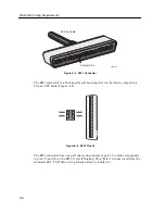
Страница 13: ...1 5 Introduction Figure 1 1 The 9H423 26 Module SMB CPU INB 9H423 26 FAST ENET F a s t E N E T FAST ENET F a s t E N E T 25 26 23 24 21 22 19 20 17 18 15 16 13 14 11 12 9 10 7 8 5 6 3 4 1 2 ...

Страница 14: ...es rebooting the unit etc The serial and revision numbers of all involved Cabletron Systems products in the network A description of your network environment layout cable type etc Network load and frame size at the time of trouble if known The device history i e have you returned the device before is this a recurring problem etc Any previous Return Material Authorization RMA numbers Phone 603 332 ...

Страница 15: ... module checking for damage If any damage exists DO NOT install the module Contact Cabletron Systems Global Call Center immediately User Accessible Components Figure 2 1 shows the various components that can be accessed by users These consist of an eight position dip switch explained in the next section replaceable PROMs and sockets for memory and flash upgrades These can be used for future upgrad...

Страница 16: ...n eight switch DIP located near the left bottom corner of the module Each switch is set according to the functions described in Table 2 1 If switch settings are changed the processor on the module must be reset using the reset switch or repowering the module for changes to take effect St Boot Prom Flash DRAM Dip Switch CNXSTATS Connector SMB1 Prom CPM i960 ...

Страница 17: ...e this switch and then reset the module s processor Once the module resets factory default parameters are placed in NVRAM You can use the default parameters or if desired enter new parameters To enter new parameters refer to the Module Local Management User s Guide 6 Force BOOTP Download This module uses BOOTP Boot Strap Protocol to download new versions of the image file into Flash Memory This pr...

Страница 18: ...per air flow and cooling 2 Attach one end of the ESD wrist strap packaged with the SmartSwitch 9000 chassis to your wrist Plug the other end into the jack for the ESD wrist strap located in the lower right corner of the SmartSwitch 9000 chassis shown in Figure 2 2 3 Slide the module into the slot and lock down both the top and bottom plastic tabs as shown in Figure 2 2 Take care that the module is...

Страница 19: ... 2 Installing the Module Metal Back Panel Module Guides Module Jack for ESD Wrist Strap Plastic Tab Warning Ensure that the circuit card is between the card guides Lock down the top and bottom plastic tabs at the same time applying even pressure ...

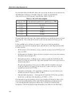
Страница 20: ...n the module or restarting the module To reset the i960 processor press the reset switch twice within three seconds To shut down the module press and hold the reset switch down for three or more seconds To restart the module after it has been shut down press and release the Reset Switch For security SNMP management can be used to disable the functions of this switch Figure 2 3 The Reset Switch SMB...

Страница 21: ...NB NIB converts data packets received from the INB into a canonical format before forwarding to the SmartSwitch ASIC All data packets destined for a front panel port the INB or the i960 are converted into the canonical format before forwarding to the SmartSwitch ASIC Network Interface Blocks NIBs check for valid data packets entering the system If an errored data packet is found the SmartSwitch AS...

Страница 22: ...mat that allows the SmartSwitch ASIC Engine to determine the proper destination port The FENIB also converts data packets from the common canonical format back to Fast Ethernet data packets for transmission out front panel ports i960 Processor Smart Switch ASIC FENIB I N B 1 2 INB NIB SMB 1 SMB 10 DC DC Converter Diagnostic Controller FENIB FENIB FENIB FENIB FENIB FENIB FENIB FENIB FENIB FENIB FEN...

Страница 23: ...ea network of endpoints having full connectivity sharing broadcast multicast and unicast packets independent of any particular physical or geographical location In other words endpoints that share a virtual LAN appear to be on a single LAN segment regardless of their actual location Changes to VLANs e g moving nodes are accomplished via software reducing network management time and expense VLANs e...

Страница 24: ...d by routing devices Figure 3 3 shows such an arrangement Each group of switches constitutes a VLAN domain Figure 3 3 VLAN Domains Endpoints on VLAN 1 Endpoints on VLAN 2 SFS Network LAN A LAN B SFS Network VLAN Switch VLAN Switch VLAN Switch SFS Network VLAN Switch VLAN Switch VLAN Switch Routing Device VLAN Domain VLAN Domain ...

Страница 25: ...n and call processing In a connection oriented network path determination is accomplished through signaling performed at call set up time Once a call is programmed no additional software intervention is required until the call is completed This type of call management operates much like a telephone network The circuit is set up data is transferred and the circuit is torn down Switches switch packe...

Страница 26: ... blocks received from the INB the INB NIB reassembles the data blocks received from the INB back into canonical frames for transmission to the SmartSwitch ASIC then from the SmartSwitch ASIC to the front panel ports System Management Buses There are two management channels within the SmartSwitch 9000 system the SMB 1 and the SMB 10 These buses provide side band management and inter module manageme...

Страница 27: ...t processor monitor the temperature and control the SMB LANVIEW diagnostic LEDs Although the system diagnostic controller and the main host processor can operate independently of each other if needed they exchange information about each other s status and overall module condition The information gathered by the diagnostic controller is available to the network manager via local remote management a...

Страница 28: ...ogram ITDM Arbitration levels The three levels of arbitration guarantee that a module will get its allocated bandwidth plus some more depending on what levels of arbitration it is participating in ITDM RAM Allocation Level 1 This level guarantees access to the backplane When a module requests access to the backplane it will get access to it when its slot number is placed onto the bus This will ens...

Страница 29: ...tration The lowest slot number module will automatically be selected as the arbitrator This module will be called the Monarch and others will be Slaves to that module If the Monarch module is removed from the chassis a re election occurs and the module with the lowest slot number is elected Monarch Cabletron s INB Bandwidth Arbitrator the third method permits the lowest slot number to use any band...

Страница 30: ...Operation 3 10 ...

Страница 31: ...ed as an aid in troubleshooting Shown in Figure 4 1 are the LANVIEW LEDs of the 9E423 26 module Figure 4 1 The LANVIEW LEDs Port Transmit FAST ENET 26 25 25 26 23 24 21 22 19 20 17 18 15 16 13 14 11 12 9 10 7 8 5 6 3 4 1 2 SMB CPU INB 9H423 26 FAST ENET System Status INB Transmit INB Receive Port Receive ...

Страница 32: ...l i e one port may be bad Yellow Green Booting Module is performing its boot process Red Reset Module is resetting Red Blinking Failed Fatal error Off Power off Module powered off Table 4 2 INB Receive LED LED Color State Green Link no activity port enabled Green Blinking Link port disabled Yellow Flashing Link activity port enabled Flashing to steady on indicates rate Red INB fault not synchroniz...

Страница 33: ...port enabled Green Blinking Link port disabled Yellow Flashing Link activity port enabled flashing to steady on indicates rate Red Fault Off No link port disabled Table 4 5 Port Transmit LEDs LED Color State Green Flashing Data activity flashing to steady on indicates rate Yellow Blinking Port in standby state Red Flashing Collision with collision rate Red Fault Off No activity port can be disable...

Страница 34: ...LANVIEW LEDs 4 4 ...

Страница 35: ...oprocessor Memory 4 Mb Local RAM expandable to 32 MB 4 Mb Flash Memory expandable to 32 MB 2 Mb Packet RAM 16 Mb DRAM expandable to 48 MB Standards IEEE 802 1D IEEE 802 3U 100BASE T IEEE 802 3U 100BASE FX Network Interfaces 2 fixed RJ21 connectors 2 fixed multi mode fiber SC connectors ...

Страница 36: ...2 ESD IEC 801 3 Radiated susceptibility IEC 801 4 EFT Service MTBF MHBK 217E 200 000 hrs MTTR 0 5 hr Physical Dimensions 35 0 D x 44 0 H x 6 0 W centimeters 13 8 D x 17 4 H x 1 2 W inches Weight Unit 1 360 7 gr 3 lbs Shipping 1 814 4 gr 4 lbs It is the responsibility of the person who sells the system to which the module will be a part to ensure that the total system meets allowed limits of conduc...

Страница 37: ...5 3 Specifications Environment Operating Temperature 5 to 40 C 41 to 104 F Storage Temperature 30 to 90 C 22 to 164 F Relative Humidity 5 to 95 non condensing ...

Страница 38: ...Specifications 5 4 ...

Страница 39: ...0 Mbps when linked to an Ethernet network it is required to maintain the capability to connect and perform at the Fast Ethernet 100 Mbps rate It is therefore necessary to have Category 5 cables and connectors for the 9H423 26 to handle signal transmission for both 10 Mbps and 100 Mbps The 9H423 26 front panel See Figure 1 1 in Chapter 1 is equipped with two multimode fiber SC connectors for 100BAS...

Страница 40: ... the cable block interference between pairs by using balancing and filtering techniques through media filters and baluns Noise is induced equally on two conductors that cancels out at the receiver Because of this and the fact that UTP cabling is lightweight thin inexpensive and versatile UTP cabling tends to be the cable of choice The typical single UTP cable contains four pairs of wires connected...

Страница 41: ...re is not an eight wire RJ45 but a 50 wire 25 pair RJ21 Figure A 3 Table A 1 RJ45 PINOUT RJ45 Pin Wire Color Code Pair EIA TIA 568A Wiring 5 White Blue Pair 1 Not used 4 Blue 3 White Orange Pair 2 RX 6 Orange RX 1 White Green Pair 3 TX 2 Green TX 7 White Brown Pair 4 Not used 8 Brown 8 7 6 5 4 3 2 1 ...

Страница 42: ... pair that is unconnected pair 25 which corresponds to pins 25 and 50 on the RJ21 It is left floating This Telco connector utilizes the standard EIA TIA 568A wiring scheme Refer to Table A 2 25 Pair Cable Contact Pins 1845n17 49 27 26 2 1 Transmit Transmit Receive Receive 50 48 47 46 45 44 43 42 41 40 39 38 37 36 35 34 33 32 31 30 29 28 27 26 25 24 23 22 21 20 19 18 17 16 15 14 13 12 11 10 9 8 7 6...

Страница 43: ...e TX 28 White Green 3 RX 2 3 Green White RX 29 White Brown 4 TX 4 Brown White TX 30 White Slate 5 RX 3 5 Slate White RX 31 Red Blue 6 TX 6 Blue Red TX 32 Red Orange 7 RX 4 7 Orange Red RX 33 Red Green 8 TX 8 Green Red TX 34 Red Brown 9 RX 5 9 Brown Red RX 35 Red Slate 10 TX 10 Slate Red TX 36 Black Blue 11 RX 6 11 Blue Black RX 37 Black Orange 12 TX 12 Orange Black TX ...

Страница 44: ...w RX 43 Yellow Green 18 TX 18 Green Yellow TX 44 Yellow Brown 19 RX 10 19 Brown Yellow RX 45 Yellow Slate 20 TX 20 Slate Yellow TX 46 Violet Blue 21 RX 11 21 Blue Violet RX 47 Violet Orange 22 TX 22 Orange Violet TX 48 Violet Green 23 RX 12 23 Green Violet RX 49 Violet Brown 24 TX 24 Brown Violet TX 50 Violet Slate 25 Unused Pair left floating 25 Slate Violet Table A 2 RJ21 PINOUT continued RJ21 P...

Страница 45: ...abling application The colors in bold designate the primary color of the wire For example pin 26 connects to a wire that is primarily white with blue stripes and pin 1 s wire is underlying blue with white stripes However because Category 5 has more twists than Category 3 vendors might manufacture the twisted pairs with the primary colors only Therefore pair one will have one white wire pin 26 twis...

Страница 46: ...uctor create electric fields in the other They interact electrically Thus consequently between the pairs there is mutual capacitance The mutual capacitance of any pair at 1 kHz and 20 C should not exceed 5 6 nF per 100 m for Category 4 and Category 5 cables Category 3 cables should not exceed 6 6 nF 100 m Capacitance Unbalance The capacitance unbalance to ground of any pair should not exceed 330 p...

Страница 47: ...as far The following table lists the maximum attenuation dB per cable pair at 20 C Refer to Table A 5 Table A 4 UTP Cable SRL Freq f MHz CAT 3 dB CAT 4 dB CAT 5 dB 1 10 12 21 23 10 16 12log f 10 21 10log f 10 23 16 20 21 10log f 10 23 20 100 23 10log f 20 Table A 5 Cable Attenuation per 100 m Freq MHz CAT 3 dB CAT 4 dB CAT 5 dB 0 064 0 9 0 8 0 8 0 256 1 3 1 1 1 1 0 512 1 8 1 5 1 5 0 772 2 2 1 9 1 ...

Страница 48: ... the near receive pair Refer to Table A 6 NEXT loss decreases as the frequency increases according to the following formula NEXT f NEXT 0 772 15log f 0 772 Propagation Delay Electrical signals in conducting wires travel at a speed dependent on the surrounding medium This is called propagation delay For Horizontal UTP cable the propagation delay for any pair at 10 MHz should not exceed 5 7ns m Tabl...

Страница 49: ...100 Mbps rates Thus consequently certain restrictions and limits are placed upon the connecting hardware and its installation as well to assure minimal effects on cable performance as listed below Attenuation Attenuation here refers to the signal power loss due to the connecting hardware Refer to Table A 7 Near End Crosstalk NEXT Loss The NEXT applies to signal coupling from one pair of metal pins...

Страница 50: ... The DC resistance between the input and output connections of the connecting hardware for 100Ω cabling shall not exceed 0 3Ω The DC resistance is measured to determine the connector s ability to transmit direct current and low frequency signals See TIA EIA 568A normative Annex A and Annex B for the reliability and transmission testing of Connecting Hardware for 100Ω UTP cabling Table A 8 NEXT Los...

Страница 51: ...tions will be stated per this case If implementing Horizontal type fiber connections see TIA EIA 568A section 12 2 The fiber will be multimode graded index 62 5 125 µm core cladding diameter The following transmission characteristics should be followed as well Refer to Table A 10 Table A 10 Backbone 62 5 125 µm Transmission Performance Wavelength nm Max Attenuation dB km Minimum Transmission Capac...

Страница 52: ...9H423 26 Cabling Requirements A 14 ...

Отзывы: