


Chapter 3: Installation
Page 3-18
NBR-SERIES Installation Guide
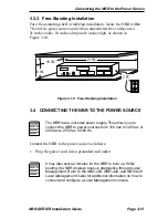
Connect an EPIM-T to a Twisted Pair Segment as follows:
1. Connect the twisted pair segment to the module by inserting the
RJ45 connector on the twisted pair segment into the RJ45 port on the
module. See Figure 3-12.
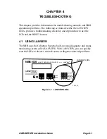
2. Check that the LNK LED for the port is on. If the LED is not on,
perform each of the following steps until it is:
a.
Check that the 10BASE-T device at the other end of the twisted
pair segment is powered.
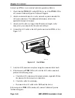
b. Verify that the RJ45 connectors on the twisted pair segment have
the proper pinouts. Figure 3-13 shows the RJ45 pinouts.
Figure 3-13
Cable Pinouts - EPIM-T RJ45 Port
c.
Check the cable for continuity.
d. Check that the twisted pair connection meets dB loss and cable
specifications outlined in Section C.1.1, 10BASE-T Twisted Pair
Network.
If you still cannot establish a link, contact Cabletron Systems Technical
Support.
TX+
TX–
RX+
RX–
2
1
3
6
TO
10BASE-T Device
Port
TX+
TX–
2
1
3
6
NOTE:
RX+/RX– and TX+/TX–
must share a common
color pair.
EPIM-T
RJ45 Port
1574-30
RJ-45 to RJ-45
RX+
RX–


